Aggregation ArchiMate

Aggregation:ArchiMate is a connector. It indicates that an element groups a number of other concepts.

The aggregation relationship has been inspired by the aggregation relationship in UML class diagrams. In contrast to the composition relationship, an object can be part of more than one aggregation.

An aggregation relationship is always allowed between two instances of the same element type.

In addition to this, the metamodel explicitly defines other source and target elements that may be connected by an aggregation relationship.


Properties:

Property Metamodel name Description
Short description ShortDescription  
Implements Implements Links to: All templates.
BreaksDownTo BreaksDownTo Links to: All templates.

Access ArchiMate

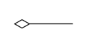
Access ArchiMate is one out of three ‘Dependency Relationships’ from the ArchiMate metamodel. IT represents a data dependency and is denoted by a dashed line.

Dependency relationships describe how elements support or are used by other elements. Three types of dependency relationship are distinguished:

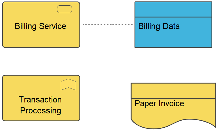
  • The servingrelationship represents a control dependency, denoted by a solid line.
  • The accessrelationship represents a data dependency, denoted by a dashed line.
  • The influencerelationship is the weakest type of dependency, used to model how motivation elements are influenced by other elements.

Note that, although the notation of these relationships resembles the notation of the dependency relationship in UML, these relationships have distinct meanings in ArchiMate notation and (usually) point in the opposite direction. One advantage of this is that it yields models with directionality, where most of the arrows that represent such supporting, influencing, serving, or realizing dependencies point ‘upwards’ towards the client/user/business. Another reason for this direction, in particular for the serving relationship, is that it abstracts from the ‘caller’ or ‘initiator’, since a service may be delivered proactively or reactively. The direction of delivery is always the same, but the starting point for the interaction can be on either end. UML’s dependency is often used to denote the latter, showing that the caller depends on some operation that is called. However, for modelling this type of initiative, the ArchiMate language provides the triggering relationship, which can be interpreted as a dynamic (i.e., temporal) dependency. Similarly, the flow relationship is used to model how something (usually information) is transferred from one element to another, which is also a dynamic kind of dependency.

If you want to learn more about the ArchiMate language, you can find the specification here

Abstraction

The Unified Modeling Language (UML) defines an Abstraction as a Relationship that relates two Elements or sets of Elements that represent the same concept at different levels of abstraction or from different viewpoints.

Semantically, an Abstraction is a Dependency that relates two NamedElements or sets of NamedElements that represent the same concept at different levels of abstraction or from different viewpoints. The relationship may be defined as a mapping between the suppliers and the clients. Depending on the specific stereotype of Abstraction, the mapping may be formal or informal, and it may be unidirectional or bidirectional. Abstraction has predefined stereotypes (such as Derive, Refine, and Trace) that are defined in UML’s Standard Profile. If an Abstraction has more than one client, the supplier maps into the set of clients as a group. For example, an analysis-level Class might be split into several design-level Classes. The situation is similar if there is more than one supplier.


Free Hand Connect

Connect symbol on a FreeHandDiagram

FreeHandConnect properties

The FreeHandConnect tab

Property  Metamodel name Description
Short description ShortDescription Short description of fragment
Breaks down to BreaksDownTo Reference to break down path
Links to: AnyThing.

The Action tab

Property  Metamodel name Description
Macro Macro This field is used to create a command language program that can be executed when the user double clicks on the symbol.
Execute on Double-click ExecuteOnDoubleClick Macro is always executed when double clicking on the symbol.
Initial value is off.

Network Connection

Network connection refers to the physical or logical connections between different components or devices within a larger infrastructure. An infrastructure can include various systems such as network devices, servers, databases, storage systems, and other components that work together to provide a particular service or functionality.

For example, in an infrastructure diagram that depicts a data center, a line might connect a server to a storage device to represent the connection between the two components. Similarly, a line might connect a switch to a router to represent the connection between the network devices.

Data Relation

A DataRelation shows the relation between two data entities.

At each end of a DataRelation there is a DataEntity, which automatically appears in the ‘From’ and ‘To’ fields in the DataRelation dialog. The roles of the DataEntities can be described and the cardinality. If a one-to-many DataRelation is created, QualiWare Lifecycle Manager will automatically update the relevant DataEntity with a foreign key.

Node Relation

Used for connecting the symbols in a deployment diagram.

NodeRelation properties

The NodeRelation tab

Property  Metamodel name Description
Show on diagram ShowOnDiagram Initial value is on.
Short description ShortDescription

The Extensions tab

Property  Metamodel name Description
Stereotype Stereotype Links to: Stereotype.
Constraints HasConstraints Links to: Constraint.
Tagged values HasTaggedValues Links to: TagDefinition.

The Ext From tab

Property  Metamodel name Description
Stereotype FromStereotype Links to: Stereotype.
Constraints FromConstraints Links to: Constraint.
Tagged values FromTaggedValues Links to: TagDefinition.

The Ext To tab

Property  Metamodel name Description
Stereotype ToStereotype Links to: Stereotype.
Constraints ToConstraints Links to: Constraint.
Tagged values ToTaggedValues Links to: TagDefinition.

Data Flow

A DataFlow is connection on a DataFlowDiagram through which information flows. A DataFlow must always be connected to a Process in one end.

Data Entity

A DataEntity represent a logical group of information – a category of information.
In the early phases of a system analysis or even a business analysis a DataEntity is used to describe physical objects like ‘Customer’, ‘Order’ or ‘Product’. Or it is used to describe important concepts in the modelled system or its surroundings.

In a later phase a DataEntity will represent a smaller normalized informationgroup.

One of the most important characteristics of a DataEntity is, that it can be uniquely identified using a relation to a Key, and that it has got non-key Attribute describing its information content.

In QualiWare Lifecycle Manager the concept of a DataEntity includes a description of the operations performed on the DataEntity during its lifecycle – i.e. from it is created for the first time in the system, until it is deleted. This is accomplished by letting the user relate a DataEntity to a series of operations – here called Methods. This object oriented approach makes it possible for the designer to separate into small reusable groups related information and functions.

When a DataEntity is created it is good practice to give it a primary key. When this is done and the OK-button on the DataEntity dialog is pressed, the key attributes is automatically transferred to the attribute link list.