IIRA – Part 1 – Part 2 – References
1 RATIONALE AND CONTEXT
This document describes a Reference Architecture for Industrial Internet Systems. It defines Industrial Internet Systems, and specifies an Industrial Internet Architecture Framework to aid in the development, documentation and communication of the Industrial Internet Reference Architecture. We begin by describing our scope.
1.1 THE INDUSTRIAL INTERNET
The Industrial Internet is an internet of things, machines, computers and people, enabling intelligent industrial operations using advanced data analytics for transformational business outcomes. It embodies the convergence of the global industrial ecosystem, advanced computing and manufacturing, pervasive sensing and ubiquitous network connectivity.
There are many interconnected systems deployed today that combine hardware, software and networking capabilities to sense and control the physical world. These industrial control systems contain embedded sensors, processors and actuators that provide the capability to serve specific operational or business purposes, but, by and large, these systems have not been connected to broader systems or the people who work with them.
The Industrial Internet concept is one that has evolved over the last decade to encompass a globally interconnected network of trillions of ubiquitous addressable devices and collectively representing the physical world.
The Industrial Internet effort will bring industrial control systems online to form large end-to-end systems, connecting them with people, and fully integrating them with enterprise systems, business processes and analytics solutions. These end-to-end systems are referred to as Industrial Internet Systems (IISs). Within these IISs, operational sensor data and the interactions of people with the systems may be combined with organizational or public information for advanced analytics and other advanced data processing (e.g., rule-based policies and decision systems). The result of such analytics and processing will in turn enable significant advances in optimizing decision-making, operation and collaboration among a large number of increasingly autonomous control systems.
Industrial Internet systems cover energy, healthcare, manufacturing, public sector, transportation and related industrial systems. As such, many IISs operate in mission critical environments and so demand high standards of security, safety and resiliency, different from those in the consumer and commercial sectors. We do not draw a clear boundary between these types of systems. Rather, we focus on the reference architectures required for industrial systems with the understanding that many concepts defined here may be applied in other types of systems.
To be effective, an IIS requires significant increases in levels of performance, scalability and efficiency. For rapid and widespread deployment, the IISs must be easily understandable and supported by widely applicable, standard-based, open and horizontal architecture frameworks and reference architectures that can be implemented with interoperable and interchangeable building blocks. These are the key motivations of this document.
1.2 REFERENCE ARCHITECTURE CONCEPTS
A reference architecture provides guidance for the development of system, solution and application architectures. It provides common and consistent definitions in the system of interest, its decompositions and design patterns, and a common vocabulary with which to discuss the specification of implementations so that options may be compared.
Example: A reference architecture for a residential house states that all residential houses need to provide one or more bedrooms, bathrooms, a kitchen and a living area. This set of rooms is accessible inside the house through doors, hallways and stairways, and from outside through a main and a back door. The house provides a safe environment against threats such as fire, hurricanes and earthquakes. The structure of the house needs to sustain snow and wind load that may be found in its local environment. The house needs to provide reasonable measures to detect and prevent unauthorized intrusions.
A reference architecture provides a common framework around which more detailed discussions can center. By staying at a higher level of abstraction, it enables the identification and comprehension of the most important issues and patterns across its applications in many different use cases. By avoiding specifics, a reference architecture allows subsequent designs to follow the reference architecture without the encumbrance of unnecessary and arbitrary restrictions.
1.3 INDUSTRIAL INTERNET REFERENCE ARCHITECTURE
The Industrial Internet Reference Architecture (IIRA) is a standard-based open architecture for IISs. To maximize its value, the IIRA has broad industry applicability to drive interoperability, to map applicable technologies, and to guide technology and standard development. The description and representation of the architecture are generic and at a high level of abstraction to support the requisite broad industry applicability. The IIRA distills and abstracts common characteristics, features and patterns from use cases well understood at this time, prominently those that have been defined in the Industrial Internet Consortium (IIC). The IIRA design is intended to transcend today’s available technologies and in so doing is capable of identifying technology gaps based on the architectural requirements. This will in turn drive new technology development efforts by the Industrial Internet community.
1.4 MAJOR COMPONENTS OF THE TECHNICAL REPORT
This technical report is divided into two parts. The first part (Chapters 1~7) provides rationale and context for the types of system under consideration (Chapter 1), and their key characteristics (Chapter 2), the architectural framework we use to describe the reference architecture (Chapter 3), and each of the component parts (‘viewpoints’) of the reference architecture (Chapter 4~Chapter7). The second part (Chapters 8~16) provides an analysis of key system concerns that require consistent analysis across the viewpoints to ensure concerted system behaviors. We conclude with references (Chapter 17).
The force behind the Industrial Internet is the integration of Information Technologies (IT) and Operational Technologies (OT). That integration is now realized in several domains as described in Chapters 4~7. Further exploration of IT/OT issues is deferred to later versions.
The IIC Vocabulary defines terms used in this document and other IIC documents [1].
1.5 NEXT STEPS
The publication of this first version of this Technical Report enables feedback. As more use cases are developed, more real systems built, and more IIC testbeds deliver results, we will continuously explore the general architecture of Industrial Internet Systems, guided by the feedback from these activities, both to refine this document and produce new works built on it. Meanwhile, we shall define which standards and technologies fit into the building blocks of the reference architecture, identify gaps and define requirements for improvement.
2 KEY SYSTEM CHARACTERISTICS AND THEIR ASSURANCE
2.1 KEY SYSTEM CHARACTERISTICS
An Industrial Internet System will exhibit end-to-end characteristics, such as safety, security or resilience. Such characteristics are emergent properties or behaviors of the IIS resulting from the properties of its various components and the nature of their interactions. Because IISs are large scale, heterogeneous, built with multi-vendor components, often broadly distributed and continuously evolving, it is a challenge to define, measure, enforce and maintain the system characteristics over time. For these reasons, we give prominent treatment to a few key system characteristics in this document.
A system characteristic is delivered through four elements:
- the system’s functional components and their interactions,
- the engineering process by which the components are created and the system assembled (system engineering),
- the way the system is used and maintained (system operations) and
- the evidence gathered throughout the full lifecycle of the components and systems. 1
Common system characteristics include upholding privacy expectations, reliability, scalability, usability, maintainability, portability and composability but three are key to the discussion of IISs because of their criticality in ensuring the core functions, rather than the efficiency, of these functions, of the system:
Safety: the condition of the system operating without causing unacceptable risk of physical injury or damage to the health of people, either directly, or indirectly as a result of damage to property or to the environment.2
Security: the condition of the system operating without allowing unintended or unauthorized access, change or destruction of the system or the data and information it encompasses.
Resilience: the condition of the system being able to avoid, absorb and/or manage dynamic adversarial conditions while completing assigned mission(s), and to reconstitute operational capabilities after casualties.
Desired system characteristics and the degree they are needed vary by system. They may be motivated by business context and values, be mandated by regulations and contractual agreements, or simply be commonly expected behaviors for a specific type of system. Note that some of these desired characteristics may be negated by unintended side effect of other unrelated system behaviors.3
To preserve these system characteristics in the evolving IISs, continuous tracking and auditing should be provided throughout the lifecycle of these systems.
The number of reports of security attacks on large enterprise and infrastructure systems is rapidly increasing, along with the level of damage they have wrought. These attacks are better organized, and employ attack techniques of ever-increasing levels of sophistication. The actors in these attacks are becoming more diverse and include anyone from insiders to casual hackers, terrorists and state-sponsored actors. Security for Industrial Internet systems from design, development, and deployment to operations must be heightened to mitigate the increased security risks. We therefore give security, a key system characteristic, a strong emphasis in this document.
2.2 SYSTEM CHARACTERISTIC ASSURANCE
System characteristics are often subject to regulations, compliance requirements and contractual agreements and thus need be measured and assessed.4
The foundation for claiming such characteristics covers three major aspects:
System engineering: Evidence supporting system characteristics must be gathered and provided, with proper tracking and certification, on the components and the system formed from their combination throughout the entire lifecycle of activities. It may include specific attributes of the software and hardware, documentation on the way it was constructed, where it was developed and by whom, and records of the types of component testing and analysis carried out, and the results thereof.
System operations: A system characteristic may depend on how a system is being used independent from the quality of the system design and components. Evidence must be available to demonstrate that the system operational processes support the characteristic. This may include evidence that the system is being used for its intended purpose and the qualification of the personnel who play a role in its operations.
System auditing: The system and its processes shall support the collection and the evaluation of metrics and logs necessary for monitoring and auditing the important characteristics. Monitoring and audit processes should be established and audit records must be maintained.
Because IISs are built from multi-vendor components and solutions, possibly composed dynamically after deployment, engineers must be able to access recorded claims and their supportive evidences of specific system characteristics in components to evaluate, select, acquire and assemble qualified components into the desired IIS.
Example: In the residential house example above, information about fire resistance, load bearing capabilities and structural integrity of the materials must be available to support the claimed “key system characteristic” of safety for individually constructed homes.
Similarly, the software in a Bluetooth-enabled device that controls the Bluetooth interface and communicates with external entities should have information available to support the assessment of the key characteristics in its fitness for a given use case. This information may include coding practices and reviews, tests and assessments done with respect to its strength to accidental inputs, malicious attacks, and the known issues and their risks in coding, design and architecture if any. It may also include regular and contingent update process and methods to address newly discovered vulnerabilities.
Supported by the information along with testable results as evidence, we can ascertain that it is, for example, safe and secure enough to use in an interface to an insulin pump.
An assurance case [2] [3] [4] is an argument supporting a claim that an IIS satisfies given requirements, in a traceable manner. Assurance cases provide a means to structure the reasoning about safety, security or resiliency in a given environment, so that system creators can gain confidence that systems will work as expected. The assurance case also becomes a key element in the documentation of the system and provides a map to more detailed information.
The activities required to construct an assurance case are similar to those that would normally occur when developing a system with required behaviors and characteristics. Assurance cases highlight and explicitly present the claims, evidence and reasoning that relates them together in a reviewable form. The explicit connections between what is claimed and the evidence used to support that claim makes the assurance case a useful tool for third parties who need to have confidence that the IIS exhibits the desired characteristics.
Assurance cases are also often used to support the iterative review and revision of the implementation of the claimed characteristics until the stakeholder gains sufficient confidence about the system displaying the claimed behaviors.
3 INDUSTRIAL INTERNET REFERENCE ARCHITECTURE
3.1 INDUSTRIAL INTERNET ARCHITECTURE FRAMEWORK
Many stakeholders are involved when considering complex systems such as those expected of Industrial Internet Systems (IISs). These stakeholders have many intertwining concerns pertinent to the system of interest. Their concerns cover the full lifecycle of the system, and their complexity calls for a framework to identify and classify the concerns into appropriate categories so that they can be evaluated and addressed systematically.
To address this need, the Industrial Internet Consortium has defined an architecture framework that describes the conventions, principles and practices for the description of architectures established within a specific domain of application and/or community of stakeholders. Based on ISO/IEC/IEEE 42010:2011 [5], the IIC Architecture Framework facilitates easier evaluation, and systematic and effective resolution of stakeholder concerns, and serves as a valuable resource to guide the development and the documentation of, and the communication about, the Industrial Internet Reference Architecture (IIRA).
The ISO/IEC/IEEE 42010:2011 standard specification codifies the conventions and common practices of architecting and provides a core ontology for the description of architectures. The IIAF adopts the general concepts and constructs in this specification, e.g. architecture and architecture framework, concern, stakeholder, and viewpoint.
The term concern refers to any topic of interest pertaining to the system. A stakeholder is an individual, team, organization or classes thereof, having an interest in a system. A viewpoint consists of conventions framing the description and analysis of specific system concerns.
The stakeholders, concerns, viewpoints and their relationship, as shown in Figure 3-1, form the basis of the Architecture Framework. The Industrial Internet Reference Architecture is fully described by the analysis on the set of specific concerns in viewpoints.
Example: Suppose we want to address the concerns of what the functional subsystems are, across what interfaces they interact and how they interact to realize the desired system behaviors. A functional decomposition of the system can make each of the subsystems easier to conceive, understand, design, implement, reuse and maintain. A component diagram may be used to describe structure of the subsystems and their interfaces,sequence diagrams the way in which the subsystems interact, and state diagrams the way in which the system or one of its subsystems behaves in response to external events. These diagrams and their associated documentation collectively describe and address the concerns of the functional viewpoint.
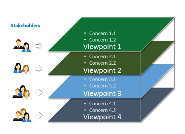
Figure 3-1 Architecture Framework
3.2 INDUSTRIAL INTERNET VIEWPOINTS
The various concerns of an IIS are classified and grouped together as four viewpoints:
- Business
- Usage
- Functional
- Implementation
As shown in Figure 3-2, these four viewpoints form the basis for a detailed viewpoint-by-viewpoint analysis of individual sets of Industrial Internet System concerns.
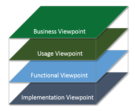
Figure 3-2 Architecture Viewpoints
The Business Viewpoint attends to the concerns of the identification of stakeholders and their business vision, values and objectives in establishing an IIS in its business and regulatory context. It further identifies how the IIS achieves the stated objectives through its mapping to fundamental system capabilities.
These concerns are business-oriented and are of particular interest to business decision-makers, product managers and system engineers.
The usage viewpoint addresses the concerns of expected system usage. It is typically represented as sequences of activities involving human or logical users that deliver its intended functionality in ultimately achieving its fundamental system capabilities.
The stakeholders of these concerns typically include system engineers, product managers and the other stakeholders including the individuals who are involved in the specification of the IIS under consideration and who represent the users in its ultimate usage.
The functional viewpoint focuses on the functional components in an IIS, their interrelation and structure, the interfaces and interactions between them, and the relation and interactions of the system with external elements in the environment, to support the usages and activities of the overall system.
These concerns are of particular interest to system and component architects, developers and integrators.
The implementation viewpoint deals with the technologies needed to implement functional components, their communication schemes and their lifecycle procedures. These components are coordinated by activities (Usage viewpoint) and supportive of the system capabilities 270 (Business viewpoint).
These concerns are of particular interest to system and component architects, developers and integrators, and system operators.
3.3 SECURITY ACROSS THE VIEWPOINTS
Security of industrial control systems today often relies on physical security, the isolation of the 275 systems and the obscurity of proprietary communication protocols. Industrial Internet Systems, on the other hand, are, by nature, connected and distributed. They continually exchange data; they are deeply integrated with enterprise systems; and they evolve over their lifetimes, converging with other IISs. Consequently, their attack surface is significantly larger than isolated industrial control systems. IISs call for an integrated approach to security spanning the physical world (including direct observability), the network world (including preservation of rights to the use of data), and the business world (including property rights and rights to make contracts). They simply cannot treat security as a separate, add-on design concern.
3.3.1 AN INTEGRATED APPROACH TO SECURITY
The IIC Reference Architecture therefore integrates security policies for physical plant, hardware, software and communication as core to system design, across all the viewpoints:
- The business viewpoint establishes the return on investment for security, in the context of other considerations such as performance or consumer satisfaction. It also defines requirements for security compliance backed by security metrics that are collected.
- The usage viewpoint strives to make security transparent to the user, minimizing their involvement, and to establish a strong differentiation between machine-to-machine protocols and human interaction.
- The functional viewpoint defines what security functions must be provided for each functional domain and how they work in concert to provide consistent security for the system as a whole.
- The implementation viewpoint applies security technologies in respect to common architecture patterns and system components.
3.3.2 THREAT MODELING AND SECURE DESIGN
All elements in an IIS are subject to various threats from various kinds of actors—anyone from employees and other insiders to casual hackers, terrorists, and state-sponsored actors, including from one’s own state when it exceeds its authority. Comprehensive threat modeling of users, assets, data and entry points considers: 5
- the solution as a whole,
- the security and privacy features,
- the features whose failures are security relevant and
- the features that cross a trust boundary separating different trust levels or domains.
Secure system design requires consideration of not only threats and the typical software issues, but also hardware design at chip and device level, physical plant design, a robust personnel security program and supply chain security.
The functional capabilities that address these threats manifest differently in each viewpoint: they need to have a business rationale and value (business viewpoint), be coordinated by specific activities and roles (usage viewpoint), have specific security functions (functional viewpoint), and dictate some architectural and deployment properties while relying on specific technologies (implementation viewpoint).
4 THE BUSINESS VIEWPOINT
4.1 ELEMENTS OF THE BUSINESS VIEWPOINT
Business-oriented concerns such as value proposition, expected return on investment, cost of maintenance and product liability must be evaluated when considering an Industrial Internet System as a solution to business problems. To identify, evaluate and address these business concerns, we introduce a number of concepts and define the relationships between them, as shown in Figure 4-1. 6
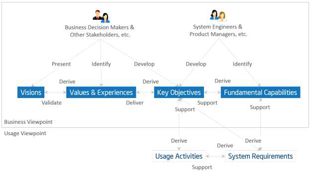
Figure 4-1 Value and Experience Model
Stakeholders have a major stake in the business and strong influence in its direction. They include those who drive the conception and development of IISs in an organization. They are often recognized as key strategic thinkers and visionaries within a company or an industry. It is important to identify these key stakeholders and engage them early in the process of evaluating these business-oriented concerns.
Vision describes a future state of an organization or an industry.7 It provides the business direction toward which an organization executes. Senior business stakeholders usually develop and present an organization’s vision.
Values and experiences reflect how the vision may be perceived by the stakeholders who will be involved in funding the implementation of the new system as well as by the users of the resulting system. These values and experiences are typically identified by senior business and technical leaders in an organization. They provide the rationale as to why the vision has merit.
Key Objectives are quantifiable high-level technical and ultimately business outcomes expected of the resultant system in the context of delivering the values and experiences. Key objectives should be measurable and time-bound. Senior business and technical leaders develop the Key Objectives.
Fundamental capabilities refer to high-level specifications of the essential ability of the system to complete specific core business tasks. 8 Key objectives are the basis for identifying the fundamental capabilities. Capabilities should be specified independently of how they are to be implemented (neutral to both the architecture and technology choices) so that system designers and implementers are not unduly constrained at this stage.
The process for following this approach is for the stakeholders first to identify the vision of the organization and then how it could improve its operations through the adoption of an IIS. From the vision, the stakeholders establish the values and experiences of the IIS under consideration and develop a set of key objectives that will drive the implementation of the vision. From the objectives, the stakeholders derive the fundamental capabilities that are required for the system.
To verify that the resultant system indeed provides the desired capabilities meeting the objectives, they should be characterized by detailed quantifiable attributes such as the degree of safety, security and resilience, benchmarks to measure the success of the system, and the criteria by which the claimed system characteristics can be supported by appropriate evidence.
4.2 SECURITY CONCERNS IN THE BUSINESS CONTEXT
In rationalizing business values and establishing key system objectives for IISs, security inevitably stands out as a key consideration in today’s environment. Security considerations are driven by two main factors:
Regulatory and compliance mandate controlling access to financial systems, protecting credit card information, upholding privacy expectations and protecting critical infrastructure. These are requirements the business must meet, no matter the cost.
Business value requires safeguarding the business investment in IISs and protecting their operations against the risk of damage brought about by security breaches. This damage may include interruption or stoppage of operations, destruction of systems, leaking sensitive business and personal data, and intellectual property, harming business reputation, and loss of customers. Heightened security objectives and standards are required to address these risks. However, they would lead to additional investment and likely extended time for system development and deployment. In some cases, they may affect user experience negatively. These additional costs must be justified to stakeholders in the context of the business risks they are addressing, sometime in terms of costs saved by averting damages.
Just like other key system objectives, there must be a way to measure and validate the continued effectiveness of security capabilities implemented in the system in meeting the security objectives. Derived from the security objectives and requirements, Security Metrics and Key Performance Indicators provide reports on compliance, regulatory, contractual or business driven, and create continuous feedback loops to increase accountability, improve effectiveness and provide quantified inputs for effective decision-making.
Security has a strong dependency on the quality of the design and implementation of a component or a system—attackers often gain access to systems by exploiting vulnerabilities in design (flaws) or implementation (bugs). The principle tenets of secure development are the same as in quality development: to apply rigor in documenting, tracking, and validating the desired features and to use known best practices to avoid introducing unknown or undesired side effects. Secure development lifecycle (SDL) is a security development process that is widely used by many organizations to avoid software vulnerabilities.9 It begins by benchmarking existing quality practices and improving any shortcomings found during initial assessments. Benefitting from the identified process improvements, the resultant product is typically both more secure and of higher quality by being more reliable and having fewer issues reported by the customers. Investments in security therefore can have measurable and sometimes immediate returns.
5 THE USAGE VIEWPOINT
5.1 ELEMENTS OF THE USAGE VIEWPOINT
The usage viewpoint is concerned with how an Industrial Internet System realizes the key capabilitiesidentified in the business viewpoint. The usage viewpoint describes the activities that coordinate various units of work over various system components. These activities—describing how the system is used—serve as an input for system requirements including those on key system characteristics and guide the design, implementation, deployment, operations and evolution of the IIS.
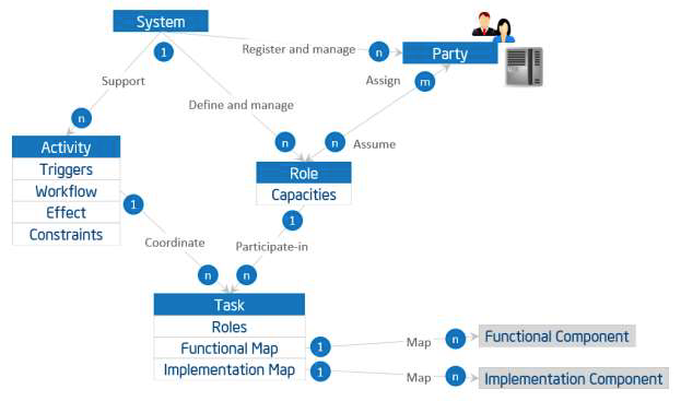
Figure 5-1 Role, Party, Activity and Task
Figure 5-1 depicts the usage viewpoint’s main concepts and how they relate to each other.
The basic unit of work is a task, such as the invocation of an operation, a transfer of data or an action of a party. A task is carried out by a party assuming a role.
A role is a set of capacities assumed by an entity to initiate and participate in the execution of, or consume the outcome of, some tasks or functions in an IIS as required by an activity. Roles are assumed by parties. A party is an agent, human or automated, that has autonomy, interest and responsibility in the execution of tasks. A party executes a task by assuming a role that has the right capacities for the execution of the task. A party may assume more than one role, and a role may be fulfilled by more than one party. A party also has security properties for assuming a role.
Note: The above definition of role is primarily operational, based on capacities that qualify an agent from a functional perspective. It does not intend to be by itself an access control model for security purposes. However, because assuming a role implies access to the IIS, it is often associated with certain security properties (such as privileges, permissions, etc.). This association in turn may require a more refined notion of role—e.g. reflective of an organization chart, user groups, etc.—that is out of scope for this section. A party also has security properties (credentials, ID…) for assuming a role, the details of which are beyond the scope of this section. A task has a role, a functional map, and an implementation map.
- A role describes, if applicable, the role(s) responsible for the execution of the task.
- A functional map describes to which functions or functional components the task maps. This can be defined only when the functional deposition of the system becomes available to perform the mapping. This mapping includes definition of inputs and outputs in the context where this task is to be executed (i.e. of a particular activity).
- An implementation map describes the implementation component(s) the task relies on for its execution. If role(s) are associated to the task, the map also defines how these roles map their capacities to the component(s) and related operations. Similarly, this property may be defined only when the implementation architecture of the system become available to perform the mapping.
Examples of tasks and roles are:
- register a new device to the edge gateway (role: administrator),
- run test procedure for passive RFID readers on processing chain X (roles: administrator, QA)
- authenticate user request (role: security agent) and
- summarize data streams from all temperature sensors on asset X (role: same as the role that initiates the edge-to-Cloud data flow processing and consolidation activity that this task is part of).
An activity is a specified coordination of tasks (and possibly of other activities, recursively) required to realize a well-defined usage or process of an IIS. An activity may be executed repeatedly. An activity has the following elements:
- A trigger is one or more condition(s) under which the activity is initiated. It may be associated with one or more role(s) responsible for initiating or enabling the execution.
- A workflow consists of a sequential, parallel, conditional, iterative organization of tasks.
- An effect is the difference in the state of the IIS after successful completion of an activity.
- Constraints are system characteristics that must be preserved during execution and after the new state is achieved, such as data integrity, data confidentiality and resilience. These characteristics may be affected by the enacting of the tasks beyond what is enforceable by the system design or its functional components alone.
An example of activity is of a device on-boarding procedure:
Trigger: Administrator approval of the new addition.
Workflow:
Task 1: Register new device to the Edge gateway.
Task 2: Register the new device in the Cloud-based management platform by automatic discovery and querying of all gateways.
Task 3: Run remote test procedure appropriate for this device type and verify that values generated are within expected range and consistent with similar devices in the proximity.
Initially, an abstract description of the activity is sufficient. During design, the activities serve as inputs to the requirements for the system, thus guiding the design of the functional architecture and its components. An activity then requires each task to be mapped to, and supported by, one or more functions. An activity is not restricted to one functional domain but may involve a sequence of tasks that span several functional domains.10
The design of the IIS now has a concrete representation of the activities by mapping its tasks to the functional and implementation components. The mappings then enable architecture and implementation verification.
5.2 COMMON SECURITY ACTIVITIES
The enforcement of security policies requires the ability to control the various endpoints and their communications involved in an activity in a generic and consistent way to ensure complete end-to-end coverage. Four common security activities are described below.
Security monitoring gathers and analyzes security-related data continuously as activities are performed. It may take different forms depending on the context of operations and on security events. For example, different tasks are appropriate before, during and after an attack.
Security auditing collects, stores and analyzes of security information related to an IIS.
Security policy management manages both automated and human-driven administrative security tasks by documenting their usage and constraints.
Cryptographic support management consists of globally interoperable key management, secure credential storage and revocation.
6 THE FUNCTIONAL VIEWPOINT
6.1 BACKGROUND
Industrial Control Systems (ICS) have been widely deployed to enable industrial automation across industrial sectors. 11 As we bring these automated control systems online with broader systems in the Industrial Internet effort, control remains a central and essential concept of industrial systems. Control, in this context, is the process of automatically exercising effects on physical systems and the environment, based on sensory inputs to achieve human and business objectives. Many control systems today apply low-latency, fine-grained controls to physical systems in close proximity, without a connection to other systems. Because of this, it is difficult to create local collaborative control, let alone globally orchestrated operations.
Some might argue that the industrial internet is the conjoining of what has been traditionally two different domains with different purposes, standards and supporting disciplines: IT and OT. 12,13 In IT (information technology), everything is reducible to bits that represent ideas in the programmer’s head and transformed in a way to produce useful inference – anything from the sum of numbers in a column to email systems to schedule optimization problems (e.g. using Simplex). The essential problem with such an approach, noted as one of the fundamental problems in the Artificial Intelligence community is the so-called ‘symbol-grounding problem’— that symbols in the machine (the numbers passed around by the processor) only correspond to world objects because of the intentions of the programmer—they have no meaning to the machine. 14,15 In OT (operations technology) ‘controls’ (traditionally analogue) have been applied directly to physical processes without any attempt to create symbols or models to be processed by the machine. For example, PID (proportional-integrative-derivative) controllers may control the voltage on a line using a particular feedback equation that is defined by the control engineer and demonstrated to work for a particular application – there is no attempt at generality and no need to divide the problem among multiple processing units. The incidence of IT into the OT world has primarily come about due to a need to network larger systems and establish control over hierarchies of machines while also wanting to inject common IT ideas into the OT world (such as scheduling and optimization of resource consumption). There has also been a move toward controls that digitally simulate the physical world and base their control decisions on the simulation model rather than a control engineer’s equation. This makes other kinds of approaches that have been examined in IT, such as machine learning, possible to apply to OT. This has also led to OT systems to be susceptible to IT problems as well, such as network denial of service attack and spoofing as well as the aforementioned symbol-grounding problem. The combination of IT and OT holds forth a great possibility of advancement – embodied cognition – to a system that can avoid the symbol grounding problem by basing its representation on the world (and not on programmer supplied models) and only its own episodic experience (and thus not be limited to human conceptions of epistemology). However even nearer term breakthroughs that will support advanced analytics based on actual world data rather than engineering models may well yield substantial improvements. The key obstacle is safety and resilience. Mission-critical OT applications are important enough that the typical levels of software reliability that are acceptable in the IT market will not be sufficient for OT. Moreover, actions in the physical world generally cannot be undone, which is a consideration that IT systems normally do not have to address.
Riding on continued advancement of computation and communication technologies, the Industrial Internet can dramatically transform industrial control systems in two major themes:
Increasing local collaborative autonomy: New sensing and detection technologies provide more, and more accurate, data. Greater embedded computational power enables more advanced analytics of these data and better models of the state of a physical system and the environment in which it operates. The result of this combination transforms control systems from merely automatic to autonomous—allowing them to react appropriately even when the system’s designers did not anticipate the current system state. Moreover, ubiquitous connectivity between peer systems enables a level of fusion and collaboration that was previously impractical.
Increasing system optimization through global orchestration: Collecting sensor data from across the control systems and applying analytics, including models developed through machine learning, to these data, we can gain insight to a business’s operations. With these insights, we can improve decision-making and optimize the system operations globally through automatic and autonomous orchestration.
These two themes have far-reaching impact on the systems that we will build, though each system will have a different focus and will balance the two themes differently.
We create the concept of functional domain to address the key concerns surrounding the functional architecture of Industrial Internet Systems. A Functional Domain is a top-level functional decomposition of an Industrial Internet System, each providing a predominantly distinct functionality in the overall system.
This functional domain model is intended to be generally applicable to IISs in many industrial verticals. However, a use case in a certain industrial vertical may place stronger emphasis on functions in one or more functional domains than in the others. In some cases, the functional domains can be implemented as a single system, combined into a single one, or split up and implemented as a part of other domains.
The decomposition of functional domains highlights the important building blocks that have been seen to have wide applicability. The set of building blocks is neither a complete nor a minimum set that any system must possess. Rather, it is intended to be a starting point for conceptualizing a concrete functional architecture within these functional domains. A use case under consideration and its specific system requirements will strongly influence how the functional domains are decomposed, so in a concrete architecture derived and extended from this reference architecture, additional functions may be added, some of the functions described here may be left out or combined and all may be further decomposed as needed.
We decompose a typical IIS into five functional domains:
- Control domain
- Operations domain
- Information domain
- Application domain
- Business domain
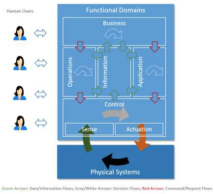
Figure 6-1 Functional Domains
Data flows and control flows take place in and between these functional domains. Fig 6-1 above illustrates how the functional domains relate to each other with regard to data and control flows. Green arrows show how data flows circulate across domains. Red arrows show how control flows circulate across domains. Other horizontal arrows illustrate some processing taking place within each domain, to process input flows and generate new forms of data or control flows.
Controls, coordination and orchestration exercised from each of the functional domains have different granularities and run on different temporal cycles. As it moves up in the functional domains, the coarseness of the interactions increases, their cycle becomes longer and the scope of impact likely becomes larger. Correspondingly, as the information moves up in the functional domains, the scope of the information becomes broader and richer, new information can be derived, and new intelligence may emerge in the larger contexts.
We describe each in turn, starting from the bottom of Figure 6-1, above the physical systems.
6.2 THE CONTROL DOMAIN
The control domain represents the collection of functions that are performed by industrial control systems. The core of these functions comprises fine-grained closed-loops, reading data from sensors (“sense” in the figure), applying rules and logic, and exercising control over the physical system through actuators (“actuation”).16 Both accuracy and resolution in timing is usually critical. Components or systems implementing these functions (functional components) are usually deployed in proximity to the physical systems they control, and may therefore be geographically distributed. They may not be easily accessible physically by maintenance personnel, and physical security of these systems may require special consideration.
Examples: Simple examples of functional components in this domain include a control room in electricity utility plant, control units in a wind-turbine, and control units in autonomous vehicles.
The control domain comprises a set of common functions, as depicted in Figure 6-2. 17 Their implementation may be at various levels of complexity and sophistication depending on the systems, and, in a given system, some components may not exist at all. We describe each in turn.
Sensing is the function that reads sensor data from sensors. Its implementation spans hardware, firmware, device drivers and software elements. Note that active sensing recursively, requires control and actuation, and may therefore have a more complex linkage to the rest of the control system, for example, an attention element to tell the sensor what is needed.
Actuation is the function that writes data and control signals to an actuator to enact the actuation. Its implementation spans hardware, firmware, device drivers and software elements.
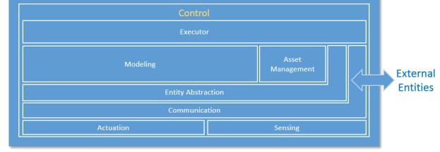
Figure 6-2 Functional Decomposition of Control Domain
Communication connects sensors, actuators, controllers, gateways and other edge systems. The communication mechanisms take different forms, such as a bus (local to an underlying system platform or remote), or networked architecture (hierarchical, hubs and spokes, meshed, pointto-point), some statically configured and others dynamically. Quality of Service (QoS) characteristics such as latency, bandwidth, jitter, reliability and resilience must be taken into account.
Within the communication function, a connectivity abstraction function may be used to encapsulate the specifics of the underlying communication technologies, using one or more common APIs to expose a set of connectivity services. These services may offer additional connectivity features that are not otherwise available directly from the underlying communication technologies, such as reliable delivery, auto-discovery and auto-reconfiguration of network topologies upon failures.
Entity abstraction, through a virtual entity representation, provides an abstraction of scores of sensors and actuators, peer controllers and systems in the next higher tiers, and expresses relationships between them. This serves as the context in which sensor data can be understood, actuation is enacted and the interaction with other entities is carried out. Generally, this includes the semantics of the terms used within the representations or messages passed between system elements.
Modeling deals with understanding the states, conditions and behaviors of the systems under control and those of peer systems by interpreting and correlating data gathered from sensors and peer systems. The complexity and sophistication of modeling of the system under control varies greatly. It may range from straightforward models (such as a simple interpretation of a time series of the temperature of a boiler), to moderately complex (a prebuilt physical model of an aircraft engine), to very complex and elastic (models built with artificial intelligence possessing learning and cognitive capabilities). These modeling capabilities, sometime referred to as edge analytics, are generally required to be evaluated locally in control systems for real-time applications. Edge analytics are also needed in use cases where it is not economical or practical to send a large amount of raw sensor data to remote systems to be analyzed even without a realtime requirement.
A data abstraction sub-function of modeling may be needed for cleansing, filtering, de- duplicating, transforming, normalizing, ignoring, augmenting, mapping and possibly persisting data before the data are ready for analysis by the models or destroyed.
Asset management enables operations management of the control systems including system onboarding, configuration, policy, system, software/firmware updates and other lifecycle management operations. Note that it is subservient to the executor so as to ensure that policies such as safety and security) are always under the responsibility and authority of the edge entity.
Executor executes control logic to the understanding of the states, conditions and behavior of the system under control and its environment in accordance with control objectives. The control objectives may be programmed or otherwise set by static configuration, be dynamic under the authority of local autonomy, or be advised dynamically by systems at higher tiers. The outcome of the control logic may be a sequence of actions to be applied to the system under control through actuation. It may also lead to interactions with peer systems or systems at higher tiers.
Similar to the case of modeling, the control logic can be:
- straightforward – a set-point program employing algorithms to control the temperature of a boiler) or
- sophisticated – incorporating aspects of cognitive and learning capabilities with a high degree of autonomy, such as deciding which obstacle a vehicle should crash into—the full school bus pulling out in front of the vehicle from the grade school or the puddle of pedestrians in front of the nursing home?18
The executor is responsible for assuring policies in its scope are applied so that data movement off its scope, use of actuators, etc. are within the bounds of such policies.
6.3 THE OPERATIONS DOMAIN
The operations domain represents the collection of functions responsible for the provisioning, management, monitoring and optimization of the systems in the control domain. Existing industrial control systems mostly focus on optimizing the assets in a single physical plant. The control systems of the Industrial Internet must move up a level, and optimize operations across asset types, fleets and customers. This opens up opportunities for added business and customer value as set out by higher-level, business-oriented domains.
Examples: Optimizing the operation of one train has obvious cost savings, but optimizing train operations and routes across a fleet yields more, and combining data from fleets owned by different railroads can optimize the utilization of the rail network within a country.
Figure 6-3 shows how operations in an IIS can be supported through a suite of interdependent operations support functions.
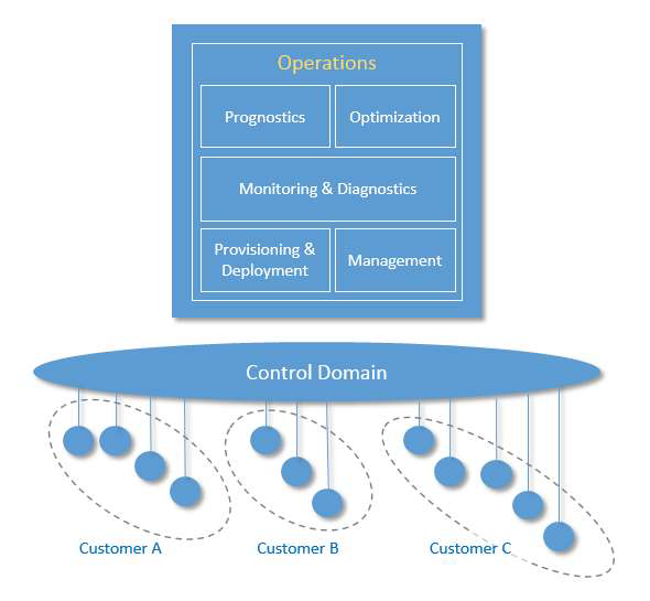
Figure 6-3 Operations Domain decomposition showing support across various customers
Provisioning and Deployment consists of a set of functions required to configure, onboard, register, and track assets, and to deploy and retire assets from operations. These functions must be able to provision and bring assets online remotely, securely and at scale. They must be able to communicate with them at the asset level as well as the fleet level, given the harsh, dynamic and remote environments common in industrial contexts. Provisioning and deployment has a strong dependency on functions in connectivity and security, trust and privacy.
Management consists of a set of functions that enable assets management centers to issue a suite of management commands to the control systems, and from the control systems to the assets in which the control systems are installed, and in the reverse direction enable the control systems and the assets to respond to these commands. For this, many of the legacy “dumb” assets need to be retrofitted to have compute, storage and connectivity capabilities. Management has a strong dependency on functions in intelligent and resilient control.
Monitoring and Diagnostics consists of functions that enable the detection and prediction of occurrences of problems. It is responsible for real-time monitoring of asset key performance indicators, collecting and processing asset health data with intelligence so that it can diagnose the real cause of a problem, and then alerting on abnormal conditions and deviations. This set of functions should assist operations and maintenance personnel to reduce the response time between detecting and addressing a problem. Monitoring and diagnostics has a strong dependency on functions in data services and analytics.
Prognostics consists of the set of functions that serves as a predictive analytics engine of the IISs. It relies on historical data of asset operation and performance, engineering and physics properties of assets, and modeling information. The main goal is to identify potential issues before they occur and provide recommendations on their mitigation. It may use the analytic functions in the information domain to realize its functions.
Optimization consists of a set of functions that improves asset reliability and performance, reduces energy consumption, and increase availability and output in correspondence to how the assets are used. It helps to ensure assets operating at their peak efficiency by identifying production losses and inefficiencies. This process should be automated, as much as it is feasible, in order to avoid potential inaccuracies and inconsistencies.
At this level, this set of functions should support key automation and analytics features including:
- Automated data collection, processing and validation.
- Ability to capture and identify major events, such as downtime, delay, etc.
- Ability to analyze and assign causes for known problems.
Optimization has a strong dependency on functions in dynamic orchestration and automatic integration. It may use the data ingestion and processing functions and analytic functions in the information domain to realize part of its functions.
6.4 THE INFORMATION DOMAIN
The Information Domain represents the collection of functions for gathering data from various domains, most significantly from the control domain, and transforming, persisting, and modeling or analyzing those data to acquire high-level intelligence about the overall system. 19 The data collection and analysis functions in this domain are complementary to those implemented in the control domain. In the control domain, these functions participate directly in the immediate control of the physical systems whereas in the information domain they are for aiding decisionmaking, optimization of system-wide operations and improving the system models over the long term. Components implementing these functions may or may not be co-located with their counterparts in the control domain. They may be deployed in building closets, in factory control rooms, in corporate datacenters, or in the cloud as a service.
Examples:
Optimizing the electricity generation level of a plant or a generator based on the condition of the facility, fuel cost and electricity price.
Changing the route of a fleet of freight trucks based on weather, traffic and the condition of the goods in the trucks.
Changing the output of an automated production plant based on condition of the facility, energy and material cost, demand patterns and logistic.
Changing the temperature set-point of a boiler based on energy cost, weather condition and usage pattern.
Figure 6-4 illustrates the functional decomposition of the information, application and business domains.
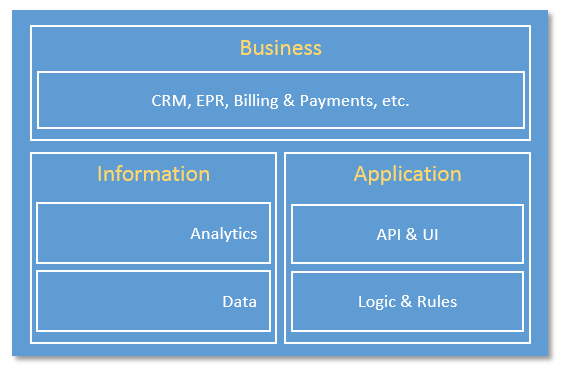
Figure 6-4 functional decomposition of Information, Application & Business Domains
Data consists of functions for:
- ingesting sensor and operation state data from all domains,
- quality-of-data processing (data cleansing, filtering, de-duplication, etc.),
- syntactical transformation (e.g., format and value normalization),
- semantic transformation (semantic assignment, context injection and other data augmentation processing based on metadata (e.g. provisioning data from the Operations Domain) and other collaborating data set,
- data persistence and storage (e.g. for batch analysis) and
- data distribution (e.g. for streaming analytic processing).
These functions can be used in online streaming mode in which the data are processed as they are received to enable quasi-real-time analytics in support of orchestration of the activities of the assets in the control domain. They may be used in offline batch mode (e.g. seismic sensor data collected and accumulated in an offshore oil platform that does not have high-bandwidth connectivity to the onshore datacenter).
Data governance functions may be included for data security, data access control and data rights management, as well as conventional data management functions related to data resilience (replication in storage, snapshotting and restore, backup & recovery, and so on).
Analytics encapsulates a set of functions for data modeling, analytics and other advanced data processing, such as rule engines. The analytic functions may be done in online/streaming or offline/batch modes. In the streaming mode, events and alerts may be generated and fed into functions in the application domains. In the batch mode, the outcome of analysis may be provided to the business domain for planning or persisted as information for other applications.
The data volume at the system level in most IIS will eventually exceed a threshold at which the traditional analytic toolsets and approaches may no longer scale in meeting the requirement in performance. Big Data storage and analytic platforms may be considered for implementing these functions.
6.5 THE APPLICATION DOMAIN
The application domain represents the collection of functions implementing application logic that realizes specific business functionalities. Functions in this domain apply application logic, rules and models at a coarse-grained, high level for optimization in a global scope. They do not maintain low-level continuing operations, as these are delegated to functions in the control domain that must maintain local rules and models in the event of connectivity loss. Requests to the control domain from the application domain are advisory so as not to violate safety, security, or other operational constraints.
The decomposition of the application domain is illustrated in Figure 6-4.
Logics and Rules comprises core logics, e.g., rules, models, engines, activity flows, etc., implementing specific functionality that is required for the use case under consideration. It is expected that there are great variations in these functions in both its contents and its constructs among the use cases.
APIs and UI represent a set of functions that an application exposes its functionalities as APIs for other applications to consume, or human user interface enabling human interactions with the application.
6.6 THE BUSINESS DOMAIN
The business domain functions enable end-to-end operations of the Industrial Internet Systems by integrating them with traditional or new types of Industrial Internet specific business functions including those supporting business processes and procedural activities. Examples of these business functions include enterprise resource management (ERP), customer relationship management (CRM), asset management, service lifecycle management, billing and payment, human resource, work planning and scheduling systems.
Examples: A predictive maintenance service for an oilrig may have an application that forecasts failures in the field. To do so, it may require a Resource Planning System to ensure the required parts are available and reserved, and it may need to connect to internal or partner’s service work schedule system and logistics management system, as well as the customer’s, to schedule the field service.
6.7 COMMON SECURITY FUNCTIONS
We summarize below a set of common security functions that may be needed in each of the functional domains and in the interactions between the functions in different domains. The common security functions are based on the international standard ‘Common Criteria for Information Technology Security Evaluation. 20 Note that this document does not cover security compliance, which will be addressed in a future Security Reference Architecture document.
- Security audit involves the collection, storage and analysis of security information related to the industrial system.
- Identity verification in communications assures the integrity of both the originator and the recipient of a communication in the industrial system.
- Cryptographic support provides the resources necessary to support the encryption and decryption operations (software and hardware).
- Data protection and privacy assures the confidentiality of data in transit and at rest. If the data contains information owned or related to a third party, it provides protection of the privacy of records as described by a security policy.
- Authentication and identity management ensures the components are only accessed by the roles specified in the security policy.
- Physical protection provides necessary protections against physical tampering and unauthorized observation as described by a security policy.
These functions contribute to various system security capabilities including:
- secured booting to a known secure state enabled through cryptographically signed software and firmware,
- enhanced trust by network and application whitelisting and reputation-based approaches (or dynamic approvals),
- enhanced privacy through mutual authentication in communication integrated with means to automatically ensure the privacy of data.
- early attack detection through rigorous anomaly detection over established norms of traffic patterns and simplified system,
- secure management of all systems and their update processes and
- automatic threat containment to minimize the damage of a successful attack.
7 IMPLEMENTATION VIEWPOINT
The implementation viewpoint is concerned with the technical representation of an Industrial Internet System and the technologies and system components required to implement the activities and functions prescribed by the usage and functional viewpoints.
An IIS architecture and the choice of the technologies used for its implementation are also guided by the business viewpoint, including cost and go-to-market time constraints, business strategy in respect to the targeted markets, relevant regulation and compliance requirements and planned evolution of technologies.21 The implementation must also meet the system requirements including those identified as key system characteristics that are common across activities and must be enforced globally as end-to-end properties of the IIS.
The implementation viewpoint therefore describes:
- The general architecture of an IIS: its structure and the distribution of components, and the topology by which they are interconnected.
- A technical description of its components, including interfaces, protocols, behaviors and other properties.
- An implementation map of the activities identified in the usage viewpoint to the functional components, and from functional components to the implementation components.
- An implementation map for the key system characteristics.
7.1 ARCHITECTURE PATTERNS
Coherent IIS implementations follow certain well-established architectural patterns, such as:
- Three-tier architecture pattern
- Gateway-Mediated Edge Connectivity and Management architecture pattern
- Edge-to-Cloud architecture pattern (This pattern contrasts with the gateway-mediated pattern as it assumes a wide-area connectivity and addressability for devices and assets.)
- Multi-Tier Data Storage architecture pattern (This pattern supports a combination of storage tiers (performance tier, capacity tier, archive tier.)
- Distributed Analytics architecture pattern.
An architecture pattern is a simplified and abstracted view of a subset of an IIS implementation that is recurrent across many IIS, yet allowing for variants. For example, an implementation of the three-tier pattern in a real IIS does not exclude multiple implementations of every tier—e.g. many instances of the edge tier—as well as many-to-many connections between instances of a tier and instances of the next tier. Each tier and its connections will still be represented only once in the pattern definition.
We describe the first two patterns in the previous list because of their stronger prevalence in IISs.
7.1.1 THREE-TIER ARCHITECTURE PATTERN
The three-tier architecture pattern comprises edge, platform and enterprise tiers. These tiers play specific roles in processing the data flows and control flows (see section 6) involved in usage activities. They are connected by three networks, as shown in Figure 7-1.
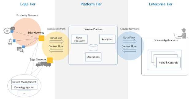
Figure 7-2 Three-tier IIS Architecture
The edge tier collects data from the edge nodes, using the proximity network. The architectural characteristics of this tier, breadth of distribution, location, governance scope and the nature of the proximity network, vary depending on the specific use cases.
The platform tier receives, processes and forwards control commands from the enterprise tier to the edge tier. It consolidates processes and analyzes data flows from the edge tier and other tiers. It provides management functions for devices and assets. It also offers non-domain specific services such as data query and analytics.
The enterprise tier implements domain-specific applications, decision support systems and provides interfaces to end-users including operation specialists. The enterprise tier receives data flows from the edge and platform tier. It also originates control commands to the platform tier and edge tier.
Note: In the above figure, functional blocks are shown in each tier. These functional blocks are indicative of the primary functional vocation of the tier, yet are not exclusively assigned to that tier. For example the ‘data transform’ function in the platform tier could also be found in the edge tier (e.g. performed by a gateway) although it would be implemented in a different way and for a different purpose. For example, ‘data transform’ at the edge is typically done in a device-specific manner through device-specific configuration and interfaces, unlike in the platform tier where it is usually supported as a higher-level service that operates on data that has been abstracted from any device source or type.
Different networks connect the tiers:
The proximity network connects the sensors, actuators, devices, control systems and assets, collectively called edge nodes. It typically connects these edge nodes, as one or more clusters related to a gateway that bridges to other networks.
The access network enables connectivity for data and control flows between the edge and the platform tiers. It may be a corporate network, or an overlay private network over the public Internet or a 4G/5G network.
The service network enables connectivity between the services in the platform tier and the enterprise tier. It may be an overlay private network over the public Internet or the Internet itself, allowing the enterprise grade of security between end-users and various services.
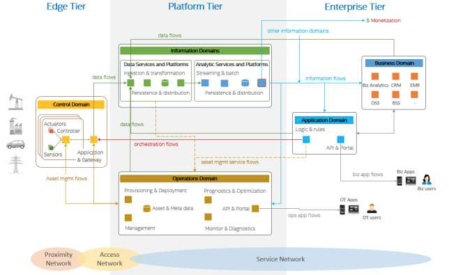
Figure 7-3 Mapping between a three-tier architecture to the Functional Domains
The three-tier architecture pattern combines major components (e.g. platforms, management services, applications) that generally map to the functional domains (functional viewpoint) as shown in Figure 7-3. From the tier and domain perspective, the edge tier implements most of the control domain; the platform tier most of the information and operations domains; the enterprise tier most of the application and business domains. This mapping demonstrates a simple functional partitioning across tiers. The actual functional mapping of IIS tiers is usually not as simplistic and is highly depends on the specific of the system use cases and requirements. For example, some functions of the information domain may be implemented in or close to the edge tier, along with some application logic and rules to enable intelligent edge computing.
Another reason why implementation tiers do not generally have an exclusive mapping to a particular functional domain is that these tiers often provide services to each other to complete the end-to-end activities of the IIS. These services—e.g. data analytics from the information functional domain—then become supportive of other functional domains in other tiers. For example:
The asset management flows (see fig. 7-2) is an expression of the operations domain component of the platform tier to manage the assets in the edge tier.
The operations domain component of the platform tier itself provides services (asset management service flows in fig. 7-2) to other components, either in the same tier or in another.
For example, the data services (information domain) component of the platform tier may request services from the operations domain component for:
- The verification of asset credentials it receives in the data flows from the edge tier.
- The query of asset metadata so it can augment the data received from the assets before the data are persisted or fed into analytics in the next stage of processing.
Similar operations domain services can be provided to the application domain components in the enterprise tier as well. Conversely, the operations domain components may use data services from the information domain component in order to get better intelligence from asset data, e.g. for diagnostics, prognostics and optimization on the assets.
As a result, components from all functional domains may leverage the same data and use analytic platforms and services to transform data into information for their specific purposes.
7.1.2 GATEWAY-MEDIATED EDGE CONNECTIVITY AND MANAGEMENT ARCHITECTURE PATTERN
The gateway-mediated edge connectivity and management architecture pattern comprises a local connectivity solution for the edge of an IIS, with a gateway that bridges to a wide area network as shown in Figure 7-4. The gateway acts as an endpoint for the wide area network while solating the local network of edge nodes. This architecture pattern allows for localizing operations and controls (edge analytics and computing). Its main benefit is in breaking down the complexity of IISs, so that they may scale up both in numbers of managed assets as well as in networking. However, it may not be suited to systems where assets are mobile in a way that does not allow for stable clusters within the local network boundaries.
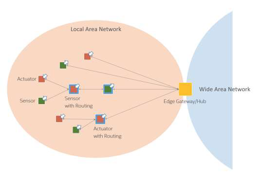
Figure 7-4 Gateway-Mediated Edge Connectivity and Management Pattern
The edge gateway may also be used as a management point for devices and assets and data aggregation point where some data processing and analytics, and control logic are locally deployed.
The local network may use different topologies.
In a hub-and-spoke topology, an edge gateway acts as a hub for connecting a cluster of edge nodes to each other and to a wide area network. It has a direct connection to each edge entity in the cluster allowing in-flow data from the edge nodes, and out-flow control commands to the edge nodes.
In a mesh network (or peer-to-peer) topology, an edge gateway also acts as a hub for connecting a cluster of edge nodes to a wide area network. In this topology, however, some of the edge nodes have routing capability. As result, the routing paths from an edge node to another and to the edge gateway vary and may change dynamically. This topology is bestsuited to provide broad area coverage for low-power and low-data rate applications on resource-constrained devices that are geographically distributed.
In both topologies, the edge nodes are not directly accessible from the wide area network. The edge gateway acts as the single entry point to the edge nodes and as management point providing routing and address translation.
The edge gateway supports the following capabilities:
- Local connectivity through wired serial buses and short-range wireless networks. New communication technologies and protocols are emerging in new deployments.
- Network and protocol bridging supporting various data transfer modes between the edge nodes and the wide area network: asynchronous, streaming, event-based and store-andforward.
- Local data processing including aggregation, transformation, filtering, consolidation and analytics.
- Device and asset control and management point that manages the edge nodes locally and acts an agent enabling remote management of the edge nodes via the wide area network.
- Site-specific decision and application logic that are perform within the local scope.
7.2 SECURE IMPLEMENTATIONS
To secure an Industrial Internet System, we outline a number of important and common security issues to be addressed in its implementation.
End-to-end security: To achieve end-to-end security in an IIS, its implementation must provide:
- protected device-to-device communications,
- confidentiality and privacy of the data collected,
- remote security management and monitoring,
- simultaneously addressing both existing technologies as well as new technologies, and
- seamlessly spanning both information technology (IT) and operational technology (OT) subsystems and processes without interfering with operational business processes.
This effort requires building in security by design rather than the often-tried and often-failed paradigm of bringing it in as an afterthought.
Securing legacy systems: Most IISs incorporate legacy systems due to the effort and capital expense involved in replacing or retrofitting these systems in industrial plants, hospitals and infrastructures. Often the legacy endpoints in these systems implement limited or no security capability in processing and in the protocols they use, and they are not modifiable to add the requisite security capability. Security of the overall system requires minimizing the attack surface of these legacy systems.
The use of security gateways is an approach to secure legacy endpoints and their protocols. A security gateway acting as proxies for the legacy endpoints bridges the legacy protocols supported by the legacy endpoints and their counterparts used by new endpoints. A security gateway isolates the attack surface introduced by the legacy endpoints and their protocols to the links from these endpoints. However, isolating the attack surface is insufficient, as we still need to detect attacks. We want to detect security attacks by analyzing the data for anomalies and abnormal behavior in a way that can be done within the threat surface, that is not all attacks will be routed through the gateway.
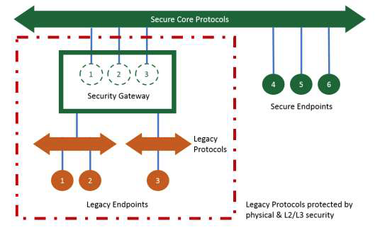
Figure 7-5 Security Gateway Deployment Pattern
Security for architectural patterns: Every architecture pattern has its own specific security requirements and challenges. In the three-tier architecture pattern, for example, there are four critical areas and operations to secure:
- end-points
- information exchange
- management and control
- data distribution and storage
End-point security: Many IISs need to embed security capabilities and policy enforcement directly in end-point devices. It includes the enablement of the remote management and monitoring of end-points for near real-time security responses during an attack as well as for proactive security measures prior to an attack. The end-point should have the ability and autonomy to defend itself and must remain resilient even when disconnected from the external security management systems. Endpoints must be able remain secure and resilient even when adjacent peer endpoints are compromised.22 The embedded security measures should include mitigating controls, countermeasures and/or remediation actions defined by security policies to minimize the risk of being compromised and the impact when being compromised.
Information exchange security: Communication and data exchanges within an IIS must be protected for authenticity, confidentiality, integrity and non-repudiation. Security solutions and practices in information technologies can be applied to network segments and applications that are built on information technologies-based infrastructures in an IIS. In some industrial environments, legacy communication technologies, protocols and processing capability may limit the full security implementation for information exchange. In these environments, the security gateway approach discussed above may be employed to protect the information exchange between the local legacy environments and the broad systems while enforcing logical isolation and physical protection for the local environments until the inadequate legacy systems are phased out over time.
Next:
Part II: Analysis of Key System Concerns
Part I described the several viewpoints and the various functional domains needed to evaluate Industrial Internet Systems. However, there are common concerns that cannot be assigned to a particular viewpoint or functional domain, such as the key system characteristics that we discussed in Chapter 2. Addressing these concerns requires consistent analysis across the viewpoints and concerted system behaviors among the functional domains and components, ensured by engineering processes and assurance programs. We call these key system concerns.
In this part, we highlight a few of these key system concerns in Industrial Internet systems as special topics and provide additional analysis on them. For some of these topics, we summarize their key elements based on prevailing and matured technologies and practices most relevant to Industrial Internet Systems. In others, we introduce some forward-looking ideas bridging what is in place now and what is needed in the near future to support the kind of IISs that we envision. These topics are:
Safety highlights a number of important considerations for safety in IISs.
Security, Trust & Privacy provides additional (to those presented in Part I) details on how to secure IISs end-to-end.
Resilience presents a few ideas on how to establish a resilient system, in reference to some of the learning from the military programs and operations.
Integrability, Interoperability and Composability suggests the direction in which IISs components should be built to support the dynamic evolution of components, including self-assembling components. It also serves as a unifying reference topic for some of the topics, such as
Connectivity, Data Management, and Dynamic Composition and Automatic Integration, all of which are to follow.
Connectivity discusses a foundational aspect of Industrial Internet—how to connect the numerous components (sensors, controller, and other systems) together to form IISs.
Data Management concerns the basic approaches for exchanging and management of data among the components in IISs.
Analytics concerns the transformation of vast amounts of data collected in an IIS into information that be used to make decisions and system optimization.
Intelligent and Resilient Control presents a conceptual model and some key ideas on how to build intelligent and resilient control.
Dynamic Composability and Automatic Integration concerns flexible adaptation to optimize services as environments change and to avoid disruptions as components are updated.
Notes
1 Broadly speaking, a lifecycle of a system includes activities for requirement specification, design, development, manufacturing, test, assembly, integration, delivery, deployment, verification, evolution and upgrade, un-deployment, and disposal of the system. We will not hereafter refer to the specific activities unless it is necessary.
2 IEC 61508, Functional Safety [25]
3 For example, a system that tracks an individual’s location on a ship to provide a man-overboard alert may also violate privacy expectations of that individual.
4 Examples of security related compliances include Common Criteria [23] and various Federal Information Processing Standards (FIPS) specifications. Examples of safety related compliance include the application of DO-178B/C to avionics software systems certification by the FAA. Compliance will not be taken up by the RA but may be addressed by future more detailed documents, as they are greatly dependent on the specific vertical and deployment scenario.
5 A structured analysis to identify, quantify, and address the security risks associated with an application or a system.
6 This approach is based on the work, An IoT Experience Framework (IoTEF), presented to the Industrial Internet Consortium by Intel Corporation and the Business Motivation Model (BMM) [24] by the Object Management Group (OMG), consistent with best practices in this domain. Some of the terminology has been changed to be consistent with the ISO/IEC/IEEE 42010:2011.
7 The concepts of vision, values and experiences and key objectives are related to the BMM concept of Ends (i.e. the results, or what needs to be achieved).
8 A capability is normally defined as “the ability to do something” although in enterprise architecture terms it is extended to be “a high-level specification of the enterprise’s ability” (MODAF). Fundamental Capabilities map to the Means aspect of the BMM, being a starting point for considering how the solution will provide the “means” to deliver the vision
9 Microsoft: Security Development Lifecycle, SDL Process Guidance Version 5.2, 2012 [26]
10 Defined in the functional viewpoint (6.1)
11 ICSs typically include supervisory control and data acquisition (SCADA) systems, distributed control systems (DCS), and other control system configurations such as skid-mounted Programmable Logic Controllers (PLC) that are often found in the industrial control sectors [30].
12 Here we use the more traditional version of the word ‘domain’.
13 Consider this an introduction to the topic—we will deal with the IT/OT problem in more detail in future versions of this and other documents.
14 http://en.wikipedia.org/wiki/Symbol_grounding_problem
15 http://en.wikipedia.org/wiki/Chinese_room
16 Possibly in a hierarchy, at several levels.
17 These set of functions are considered essential to many control systems in the control domain. However, they may exist in other domains as well.
18 Such ethical choices are the subject of ‘trolley problems’ and are indicative of deep policy issues that typically should not be left up to a programmer to decide. See, e.g., [33]
19 Possibly in a hierarchy, at several levels.
20 The Common Criteria for Information Technology Security Evaluation (abbreviated as Common Criteria or CC) is an international standard (ISO/IEC 15408) [23] for computer security certification.
21 This version of the RA will not attempt to address regulatory and compliance requirements. These are substantially different by vertical, and may be addressed in more detail in future documents.
22 Both in the physical and the process sense.