A branching mechanism that determine the possible paths of execution based on user specified conditions.
QLM Users
Data Type
In the context of a Class Diagram, a datatype is a specialized kind of classifier that represents a simple, non-composite type of data. It is used to define the types of attributes, parameters, and return values for classes and their operations. Unlike classes, datatypes typically don’t have operations or behaviors associated with them, focusing primarily on the structure of the data.
When creating a Class Diagram, you can use predefined datatypes (provided by the modeling tool or the underlying modeling language, such as UML) or define your own custom datatypes to represent specific data structures needed for your system. These custom datatypes can then be used as templates for defining the types of attributes or operation parameters and return values in your classes.
For example, consider a Class Diagram for a software system that manages books in a library. You might define a custom datatype called “ISBN” to represent the International Standard Book Number format. In this case, the “ISBN” datatype can be used as a template for the “isbn” attribute in the “Book” class. This helps ensure consistent representation and interpretation of ISBN data across the system.
Data Relation
A DataRelation shows the relation between two data entities.
At each end of a DataRelation there is a DataEntity, which automatically appears in the ‘From’ and ‘To’ fields in the DataRelation dialog. The roles of the DataEntities can be described and the cardinality. If a one-to-many DataRelation is created, QualiWare Lifecycle Manager will automatically update the relevant DataEntity with a foreign key.
Node Relation
Used for connecting the symbols in a deployment diagram.
NodeRelation properties
The NodeRelation tab
| Property | Metamodel name | Description |
| Show on diagram | ShowOnDiagram | Initial value is on. |
| Short description | ShortDescription |
The Extensions tab
| Property | Metamodel name | Description |
| Stereotype | Stereotype | Links to: Stereotype. |
| Constraints | HasConstraints | Links to: Constraint. |
| Tagged values | HasTaggedValues | Links to: TagDefinition. |
The Ext From tab
| Property | Metamodel name | Description |
| Stereotype | FromStereotype | Links to: Stereotype. |
| Constraints | FromConstraints | Links to: Constraint. |
| Tagged values | FromTaggedValues | Links to: TagDefinition. |
The Ext To tab
| Property | Metamodel name | Description |
| Stereotype | ToStereotype | Links to: Stereotype. |
| Constraints | ToConstraints | Links to: Constraint. |
| Tagged values | ToTaggedValues | Links to: TagDefinition. |
Data Object
Data Objects provide information about what Activities require to be performed and/or what they produce, Data Objects can represent a singular object or a collection of objects. Data Input and Data Output provide the same information for Processes.
![]()
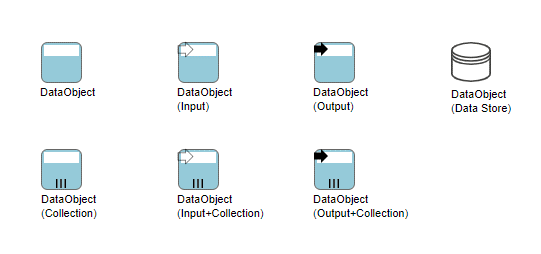
In BPMN, a Data Object is considered an Artifact and not a Flow Object. They are considered an Artifact because they do not have any direct effect on the Sequence Flow or Message Flow of the Process, but they do provide information about what the Process does. That is, how documents, data, and other objects are used and updated during the Process. While the name Data Object may imply an electronic document, they can be used to represent many different types of objects, both electronic and physical.
In general, BPMN will not standardize many modeling Artifacts. These will mainly be up to modelers and modeling tool vendors to create for their own purposes. However, equivalents of the BPMN Data Object are used by Document Management oriented workflow systems and many other process modeling methodologies. Thus, this object is used enough that it is important to standardize its shape and behavior.
As an Artifact, Data Objects generally will be associated with Flow Objects. An Association will be used to make the connection between the Data Object and the Flow Object. This means that the behavior of the Process can be modeled without Data Objects for modelers who want to reduce clutter. The same Process can be modeled with Data Objects for modelers who want to include more information without changing the basic behavior of the Process.
In other cases, the same Data Object will be shown as being an input, then an output of a Process. Directionality added to the Association will show whether the Data Object is an input or an output. Also, the state attribute of the Data Object can change to show the impact of the Process on the Data Object.
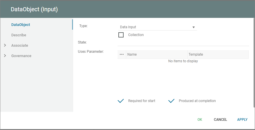
State is an optional attribute that indicates the impact the Process has had on the Data Object. Multiple Data Objects with the same name MAY share the same state within one Process. Examples of state could be: initiated, logged, registered.
The Uses Parameter field can be used to define specific parameters, values, or conditions that must exist to permit the DataObject to be created or used as input to a process/activity.
The Required for Start checkbox in QualiWare can specify whether or not the DataObject MUST exist for the Activity to start.
The Produced at Completion checkbox can be checked if the DataObject is output of an Activity and produced at the completion of the work associated with the Activity.

Data Flow
A DataFlow is connection on a DataFlowDiagram through which information flows. A DataFlow must always be connected to a Process in one end.
Data Entity
A DataEntity represent a logical group of information – a category of information.
In the early phases of a system analysis or even a business analysis a DataEntity is used to describe physical objects like ‘Customer’, ‘Order’ or ‘Product’. Or it is used to describe important concepts in the modelled system or its surroundings.
In a later phase a DataEntity will represent a smaller normalized informationgroup.
One of the most important characteristics of a DataEntity is, that it can be uniquely identified using a relation to a Key, and that it has got non-key Attribute describing its information content.
In QualiWare Lifecycle Manager the concept of a DataEntity includes a description of the operations performed on the DataEntity during its lifecycle – i.e. from it is created for the first time in the system, until it is deleted. This is accomplished by letting the user relate a DataEntity to a series of operations – here called Methods. This object oriented approach makes it possible for the designer to separate into small reusable groups related information and functions.
When a DataEntity is created it is good practice to give it a primary key. When this is done and the OK-button on the DataEntity dialog is pressed, the key attributes is automatically transferred to the attribute link list.
Database
Storage of data in an organization.
Object
An instance of a class.
Object properties
The Object tab
| Property | Metamodel name | Description |
| Number | Number | |
| Group | ||
| Persistent | IsPersistent | Initial value is on. |
| Transient | IsTransient | Initial value is off. |
| Static | IsStatic | Initial value is off. |
| Style | Style |
Choices are: Hexagon Rectangle OMT |
| Property | Property |
Choices are: Root Leaf Abstract |
| Active | Active | Initial value is off. |
| Display as | DisplayType |
Choices are: Normal Anonymous All |
| Instance of | InstanceOf | Links to: Class, Actor, Component. |
| Show on diagram | ShowOnDiagram | Initial value is off. |
| Value instance | ValueInstance | |
| Has object diagram | HasObjectDiagram | Links to: ClassDiagram. |
The Extensions tab
| Property | Metamodel name | Description |
| Stereotype | Stereotype | Links to: Stereotype. |
| Constraints | HasConstraints | Links to: Constraint. |
| Tagged values | HasTaggedValues | Links to: TagDefinition. |
Object Association
Object association refers to the relationship between different objects or components within a system, where one object is associated or linked to another object. Object association can be used to represent various types of relationships, such as ownership, collaboration, or interaction between different objects or components.
For example, in a system where a customer places an order for a product, the object association might be illustrated through a line connecting the customer object to the order object, and another line connecting the order object to the product object. The lines would represent the associations between the objects, since the customer is associated with the order, and the order is associated with the product.
The ObjectAssociation tab
| Property | Metamodel name | Description |
| Show | ShowShortDescription | Check to show short description on diagram Initial value is on. |
| Short Description | ShortDescription | Short verbal description of this relation |
| Role | FromRole | Verbal description of the role of the starting InformationConcept. |
| Show | ShowFromRole | Check to show role on diagram. Initial value is on. |
| Group | ||
| Role | FromRole | Verbal description of the role of the starting InformationConcept. |
| Show | ShowFromRole | Check to show role on diagram. Initial value is on. |
| Cardinality | FromCardinality | Min. and max. cardinality for the starting InformationConcept for each ending. Choices are: 0:1 1:1 0:M 1:M |
| Role | ToRole | Verbal description of the role of the ending InformationConcept. |
| Show | ShowToRole | Check to show role on diagram. Initial value is on. |
| Group | ||
| Role | ToRole | Verbal description of the role of the ending InformationConcept. |
| Show | ShowToRole | Check to show role on diagram. Initial value is on. |
| Cardinality | ToCardinality | Min. and max. cardinality for the ending InformationConcept for each starting. Choices are: 0:1 1:1 0:M 1:M |