Application Communication Diagram

ea3-sys
EA3 artifact A-2: Application Communication Diagram

The A-2 artifact compliments the A-1 Application Interface Diagram by providing a description of how data is communicated between systems throughout the enterprise, and includes specifics about links, paths, networks, and media.

appl-comm

Application Interface Diagram

ea3-sysEA3 artifact A-1: Application Interface Diagram

The Application Interface Diagram shows the logical and/or physical interfaces between the enterprise’s systems for information, production, etc. where information and/or other resources are exchanged.

appl-interface

Object Library

ea3-info

EA3 artifact D-10: The Object Library

GEM: Generic Enterprise Model
A GEM is an object library that defines the classes of objects that are generic across a type of enterprise, such as manufacturing or banking, and can be used (instantiated) in defining a specific enterprise.

A GEM is composed of the following:

  • a set of object classes structured as a taxonomy (that is, each object is linked to one or more other objects by a subclass-superclass relationship plus a definition of how a class refines its superclass);
  • for each object class, a set of relations linking it to other object classes plus a definition of the intended meaning of each relation;
  • for each object class, a set of attributes plus a definition of the intended meaning of each attribute.

Mark S. Fox and Michael Gruninger: Enterprise Modeling. AI Magazine Volume 19 Number 3 (1998)


Data Dictionary

ea3-info

EA3 artifact D-9: The Data Dictionary

The Data Dictionary provides a comprehensive listing of the data entities that are collected and maintained by the enterprise, including standards for the attribute fields, keys, and relationships. The Data Dictionary may also include a ‘library’ of re-useable Data Objects that use UML methods.

Examples

Daily use

Field Name Data Type Field Length Description Key Sample
CustomerName String 15 Name of Customer/Supplier Thompson, Bob
CustomerPhone String 15 Phone of Customer/Supplier (509) 555-1298
CustomerAddress String 45 Address of Customer/Supplier 1698 Mellowbrook Road
CustomerState String 15 State of Customer/Supplier WA
CustomerZip Int 9 Zip of Customer/Supplier 980045890
CustomerInventory Int 15 Customer Inventory in Queue 16
CustomerID Int 10 Customer Primary Key PK 948920
ProductName String 15 Product Name Hammer
ProductCategory String 15 Category of Product Tools
ProductID Int 30 Primary Key for Product FK 5432
ProductInventory Int 6 Product Inventory in Warehouse 32
CustomerAcct Int 15 Customer Account Number FK 84392795
PurchaseDate Datetime 8 Date of Customer Purchase FK 12121986
ShipDate Datetime 8 Date of Customer Product Ship FK 12121986

Event Sequence Diagram

ea3-info

EA3 artifact D-8: The Event-Trace Diagram

The Event-Trace Diagram allows the tracking of actions in a set of scenarios or operational threads. Each diagram should focus on a critical sequence of events and a description of the event scenario should be provided.

With time proceeding from the top of the diagram to the bottom, a specific diagram lays out the sequence of information exchanges that occur between business nodes for a given scenario. These information exchanges are associated with events and actions (see Information Exchange Matrix). The direction of the event arrows shows flow of control, in terms of the business process, from node to no.

eventtrace

State-Transition Diagram

ea3-info

EA3 artifact D-7: The State Transition Diagram

The State Transition Diagram uses the notation from the Unified Modeling Language (UML) to show how the lifecycle of a specific data object. This diagram shows changes to attributes, links, and/or behavior(s) of the “On-Line Order” object that are a result of internal or external system events which trigger changes in state.

state-transision

CRUD Matrix

ea3-info

EA3 artifact D-6: The Activity/Entity Matrix

An Activity/Entity Matrix is developed by mapping which data entities are affected by related line of business activities. Often called a ‘CRUD’ matrix because it identifies the basic types of transformations that are performed on data (Create, Read, Update, Delete) through a process.

crud

Physical Data Model

ea3-info

EA3 artifact D-5: Physical Data Model

The Physical Data Model (PDM) is used to describe how the information represented in the Logical Data Model is actually implemented in an information system. There should be a mapping from a given Logical Data Model to the PDM. The PDM is a composite model whose components can vary greatly, as shown in the template below. For some purposes, an entity-relationship style diagram of the physical database design will suffice. The Data Definition Language may also be used in the cases where shared databases are used to integrate systems.

Physical Data Model Provides
Message Format:

  • Standards Reference
  • Message Type(s)
  • Message Fields with Representation
  • Map from the Logical Data Model to the Message Fields

File Structure:

  • Standards Reference
  • Record and File Descriptions
  • Map from Logical Interface Model to Record Fields

Physical Schema:

  • DDL or ERA Notification with sufficient detail to generate the schema
  • Map from the Logical Data Model to the Physical Data Model with Rationale

Data Flow Diagram

ea3-info

EA3 artifact D-4: Data Flow Diagram

The Data Flow Diagram (DFD) is intended to show the processes within a system that exchange data, and how those exchanges occur. This artifact compliments the B-1 Business Process Diagram, and can be decomposed to show additional detail.

dfd1

dfd2

uml-activitydiagram

Information Exchange Matrix

ea3-info
EA3 artifact D1.1 / D-2a: The Information Exchange Matrix

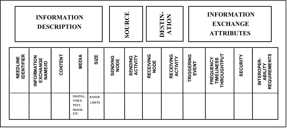
The Information Exchange Matrix describes relevant attributes of data exchanges between systems. These attributes include size, logical specification of the information i.e., media, timeliness required, and the security classification and properties of the information.

Information exchanges express the relationships across four important aspects of the architecture (information, activities, locations, and times) with a focus on the specific aspects of the information flow. Information exchanges identify which business nodes exchange what information during the performance of what activities and in response to which events. Additional information on who is performing the activity can be added, if needed for security analysis. The detailed information in the Information Exchange Matrix may be hard to collect but it is necessary to fully understand the information flow in the enterprise and its security aspects.

The matrix also identifies the event that triggers the information exchange (e.g., set schedule or citizen request). The matrix keys the exchange to the producing and using activities and nodes and to the needline (from the Node Connectivity Diagram) the exchange satisfies. The Information Exchange Matrix partitions each high-level needline into its component parts, i.e., into distinct information exchanges between business nodes. An example format for this artifact is provided below. Additional characteristics may be added to the D-1 matrix based on the purpose or goals of the enterprise.

infoexch