Requirements Realization Viewpoint : Archimate

Concerns: Architecture strategy and tactics, motivation
Purpose: Designing, deciding, informing
Scope: Motivation

The requirements realization viewpoint allows the designer to model the realization of requirements by the core elements, such as business actors, business services, business processes, application services, application components, etc. Typically, the requirements result from the goal refinement viewpoint.

In addition, this viewpoint can be used to refine requirements into more detailed requirements. The aggregation relationship is used for this purpose.

Migration Viewpoint : Archimate

Concerns: History of models
Purpose: Designing, deciding, informing
Scope: Implementation and Migration

The migration viewpoint entails models and concepts that can be used for specifying the transition from an existing architecture to a desired architecture.

Application Architecture Diagram

Purpose: The purpose of an Application Architecture Diagram is to show the structure of an Information System and its relations to other Information Systems.

Core concerns: The Application Architecture Diagram is used to document the application/systems layer. It can show information flows and system dependencies between Information Systems as well as depict system components and system areas.

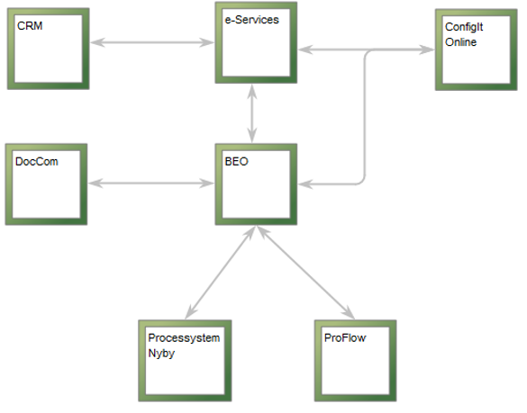
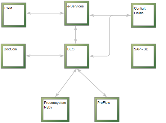
The above picture shows an example of an Application Architecture Diagram depicting an overview of the Information Systems related to BEO. The information systems are connected by arrows that symbolize system dependencies.

Other functionalities: Application Architecture Diagrams can be analyzed in QualiWare via the toolbar for Application Portfolio Management. The Application Portfolio Management tools offers analysis for redundant functionalities, performance matrix generation, system heat map generation, asset lifecycle view (se below picture), lifecycle dependencies, and capabilities delivered by multiple information systems.

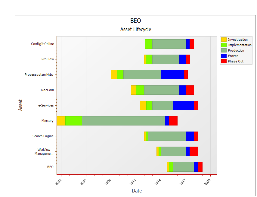
The above picture shows the Asset Lifecycle of the Information System ‘BEO’ and the Information Systems related to it is shown. The information depicted is pulled from the Information Systems’ metadata.

Relation to other templates: The elements depicted in the Application Architecture Diagram can be described in further detail in another Application Architecture Diagram, or in related diagrams such as a Data Flow Diagram.

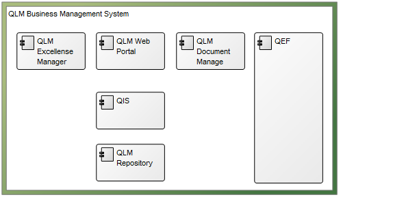
The above picture shows an example of a more detailed view of an information system. In this Application Architecture Diagram the System Components are visible.

For documentation of a physical or hardware layer, the Infrastructure Diagram template can be used.

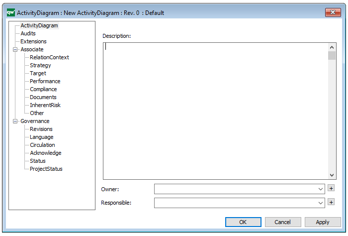
Properties and metadata: The Application Architecture Diagram can for example retain the following information:

  • A description of the diagram
  • Link to the owner of the application architecture
  • Link to the one responsible for the application architecture
  • Associated documents, diagrams and other objects
  • Inherent Risk detailing risk considerations
  • Governance information detailing information about the published diagram and who has been involved in the approval of the diagram

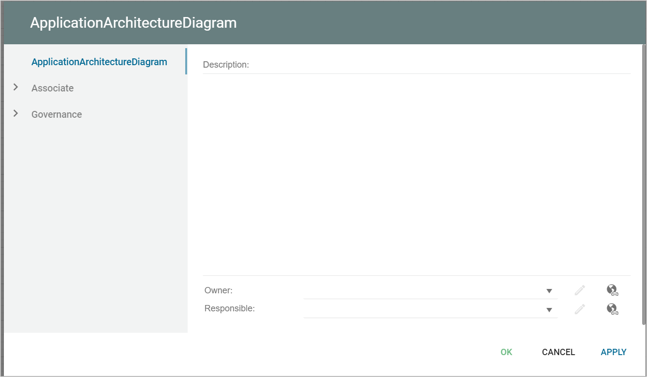
The above picture shows the properties dialogue window for the Application Architecture Diagram where you can view and edit the diagram’s properties.

Activity Diagram

Purpose: The purpose of the Activity Diagram is to show the overall flow of control through workflows for computational and organizational processes using the UML standard.

Core concerns: The Activity Diagram enables you to document stepwise activities and actions with support for choice, iteration and concurrency. The template allows you to connect the following objects using either Control Flows, Object Flows or Exception Handlers:

Below, you can see two different examples of an Activity Diagram. The first illustrates a structure for an ideation process, the second shows the process for Booking an order – divided into two different Activity Partitions:

ActivityDiagram_2

ActivityDiagram_1

Relation to other templates: The Activity Diagram can be used instead of a Workflow Diagram or a Business Process Diagram, though the different languages have their own pros and cons. The Activity Diagram is part of the UML templates QualiWare supports along with the Communication Diagram, Deployment Diagram, Class Diagram, Composite Structure Diagram, State Diagram, Package Diagram, Component Diagram, Sequence Diagram, Use case diagram and Timing Diagram.

Properties and metadata: The Activity Diagram ­­­­can for example retain the following information:

  • A description of the diagram
  • Link to the owner of the diagram
  • Link to the one responsible for the diagram
  • Audits (auto generated information regarding its current state and access rights)
  • Extensions: Stereotypes, constraints and tagged values
  • Associated documents, diagrams and other objects
  • Inherent Risk detailing risk considerations
  • Governance information detailing information about the published diagram and who has been involved in the approval of the diagram

The above picture shows the properties dialogue window for the Activity Diagram where you can view and edit the diagram’s properties in QualiWare Lifecycle Manager.

For more information: about the UML and Activity Diagram, please visit the Object Management Group’s Website, where you can find the complete specification.