Continuity of Operations Plan

ea3-secEA3 artifact SP-6: Continuity of Operations Plan

The Continuity of Operations Plan (COOP) uses a standard format for describing where all or part of the enterprise will relocate to if the normal operating location cannot be occupied for an extended period (more than a few days) due to a natural or man-made event.

The activation of the COOP relocation site may have to be accomplished in the midst of a local or national disaster that makes clarity, brevity, completeness, and flexibility (backups) key to success. The following are some of the recommended elements in a COOP document:

1. COOP Activation. Conditions for Activating the COOP.

2. COOP Roles and Responsibilities. A matrix of the roles and responsibilities (by position) of all personnel throughout the enterprise who are involved in activating the COOP. Alternates are provided for each position.

3. COOP Checklist. A step-by-step checklist of actions for each person participating in the COOP.

4. COOP Relocation Site Map and Directions. How to get to the COOP site from various probable routes.

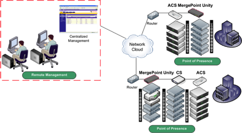
5. COOP Relocation Site Activation. The process for activating the COOP site, establishing internal/external communications, and reconstituting key enterprise functions at the COOP site.

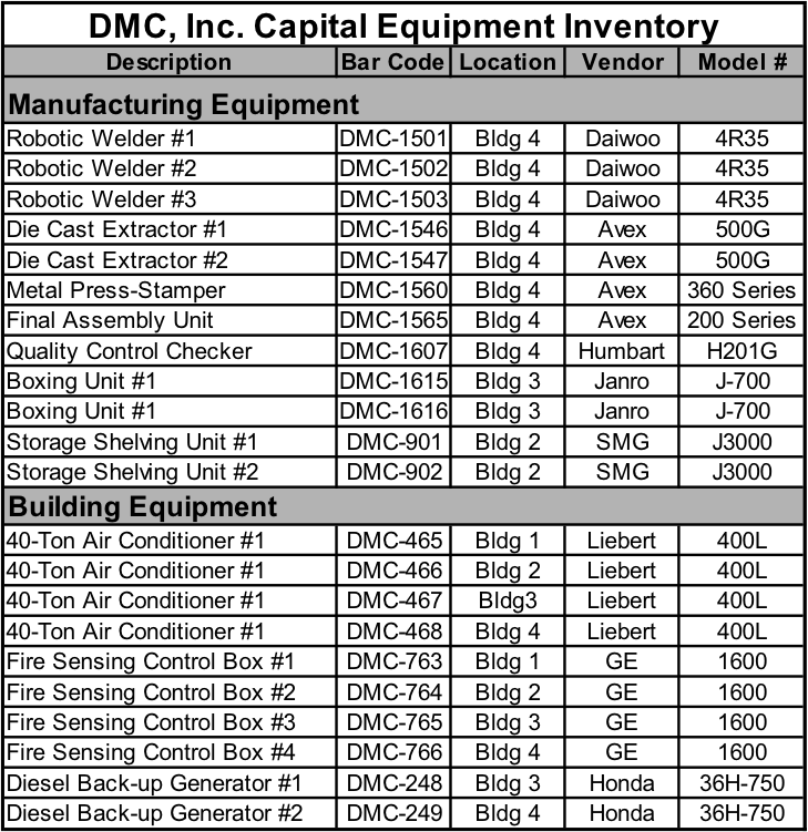
6. COOP Relocation Site Inventory. An inventory of systems, equipment, and supplies at the COOP relocation site, along with the person(s) responsible for ensuring that the systems are operational and the equipment is present when needed.

7. COOP Relocation Site De-Activation. Procedures for de-activating the COOP site and restoring it to a ‘ready status’ after a real relocation event or training exercise.

Enterprise Functions Have to Relocate

Disaster Recovery Plan

ea3-secEA3 artifact SP-5: Disaster Recovery Plan

The Disaster Recovery Plan is an assessment matrix and set of procedures to handle outages in various business and/or technology capabilities that do not require the enterprise to relocate its operations.  Outages can be caused by natural or man-made events (e.g. fire, flood, power outage).

The activation of the Disaster Recovery Plan may have to be accomplished in the midst of a natural or man-made disaster that makes clarity, brevity, completeness, and flexibility (backups) key to success. The following are some of the recommended elements in a Disaster Recovery Plan:

1. Disaster Recovery Activation. Conditions for Activating the COOP.

2. Recovery Roles and Responsibilities. A matrix of the roles and responsibilities (by position) of all personnel throughout the enterprise who are involved in activating the COOP. Alternates are provided for each position.

3. Disaster Impact and Recovery Assessment. A standard matrix for assessing the type and duration of the outage, as well as the systems and functions throughout the enterprise that are affected. Depending on the type of outage and the projected period of outage (minutes, hours, days), the recovery procedure may differ.

4. Recovery Procedures. The procedures that are used to restore the business and/or system functions that have been disrupted. Examples include:

  • Electrical Outage
  • Air Conditioning/Heating Outage
  • Building Damage (Fire, Flood, Earthquake)
  • Room Damage (Fire, Flood, Earthquake)
  • Virus Infection of Information System(s)
  • Loss of Internal or External Data Communications
  • Loss of Internal or External Telephone Communications

Enterprise Functions Do Not Relocate

Continuous Monitoring Procedures

ea3-secEA3 artifact SP-4: Continuous Monitoring Procedures

Continuous monitoring is the process and technology used to detect compliance and risk issues associated with an organization’s financial and operational environment.

Three operational disciplines:

  • Continuous Audit
  • Continuous Controls Monitoring
  • Continuous Transaction Inspection
continuousmonitoring

Certification & Accreditation

ea3-secEA3 artifact SP-3: Certification & Accreditation Documentation

The System Accreditation Document uses a standard format for evaluating the security status of information systems throughout the enterprise.  There are a number of parts to a system security accreditation as are illustrated in the example.

  1. System Security Plan. This opening section of the System Accreditation Document provides an overview of the business context that the information system operates in, states the current security status of the system (last accreditation), and summarizes the contents and finding of the other accreditation documents.
  2. System Risk Assessment. This section of the document uses a standardized format for showing areas of risk to the information system in the four primary areas security threat areas that are covered in artifact SP-2; physical, data, operational, and personnel. Assigns a level of risk based on the business context for system operations and the type of system data to be protected. Provides security risk remediation strategies (how to avoid a security risk, or deal with it if a problem occurs) for each area of risk that is identified.
  3. System Test and Evaluation. Also called a system ‘penetration test.’ The System Test and Evaluation (ST&E) section of the document provides the results of a live test that attempts to enter the system through other-than-normal log-in procedures, as well as attempts to overwhelm the system (denial of service attack), or infect the system with an active virus, worm, or other type of problematic element that reduces or eliminates information system functionality.
  4. Remediation Plan. This section of the document provides the status of corrective actions taken to fix all of the security risks found during the risk assessment/ST&E.
  5. Approval to Operate. This section of the document is the formal (signed) approval to operate the information system that is provided by the designated person in the enterprise (usually the Chief Information Officer or the IT Security Manager).

Security and Privacy Plan

ea3-secEA3 artifact SP-2: Security Plan

The Security Plan provides both high-level and detailed descriptions of the security program that is in effect throughout the enterprise.  This includes physical, data, personnel, and operational security elements and procedures.

Chapter 11 in Bernard’s book provides additional detail on Security Plans.

  1. Introduction
    • Purpose of the IT Security Program
    • Principles of IT Security
    • Critical Success Factors
    • Intended Outcomes
    • Performance Measures
  2. Policy
    • Executive Guidance
    • Technical Guidance
    • Applicable Law and Regulations
    • Standards
  3. Reporting Requirements
    • IT Security Program Roles and Responsibilities
    • IT Security Program Schedule and Milestones
    • IT Security Incident Reporting
  4. Concept of Operations
    • IT Security Threat Summary
    • IT Security Risk Mitigation
    • Integration with Enterprise Architecture
    • Component/System Security Plans
  5. Security Program Elements
    • Information Security
    • Personnel Security
    • Operational Security
    • Physical Security
  6. Standard Operating Procedures
    • Test and Evaluation
    • Risk Assessment
    • Certification and Accreditation
    • Disaster Recovery/Continuity of Operations
    • Records Protection and Archiving
    • Data Privacy

Security Controls Catalog

ea3-secEA3 artifact SP-1: Security Controls Catalog and Solutions Description

The Security Controls Catalog is

The Security Solutions Description provides a high-level view of how security is provided for selected resources throughout the enterprise.  The solutions cover four dimensions of security: physical, data, personnel, and operations and may include diagrams or matrices.

Operational Security

In the area of operational security, the Security Program should promote the development of standard operating procedures (SOPs) for all EA components that support line of business operations. SOPs should also be developed for recovery from major outages or natural disasters, and for enabling the continuity of operations if all or part of the enterprise becomes disabled.

Data Security

In the area of information security, the Security Program should promote security-conscious designs, information content assurance, source authentication, and data access control. The assessment of types of data being handled for privacy protection concerns should also be done (e.g. customer credit data or employee SSNs).

Personnel Security

In the area of personnel security, the Security Program should promote user authentication and IT security awareness, and new user/recurring training. badges, biometrics, card swipe units, cipher locks, and other methods of combining personnel and physical security solutions should be implemented.

Physical Security

The elements of physical security that should be captured in the EA include protection for the facilities that support IT processing, control of access to IT equipment, networks, and telecommunications rooms, as well as fire protection, media storage, and disaster recovery systems.


Facility Blueprints

ea3-infraEA3 artifact I-12: Facility Blueprints

This artifact is a full set of electronic blueprints for all of the physical buildings and rooms throughout the enterprise.  The blueprints aid in planning and decision-making regarding the placement of workspaces, production facilities, warehouses, networks and other business functions.

Asset Inventory

ea3-infraEA3 artifact I-11: Asset Inventory

The Asset Inventory lists all of the hardware and software on the enterprise’s voice, data, and video networks throughout the enterprise.  The list may include bar code numbers or other unique identifiers.

assetinventory

Capital Equipment Inventory

The Capital Equipment Inventory lists all of the non-information technology capital (depreciable) equipment in each line of business throughout the enterprise.  The list may include bar code numbers or other unique identifiers.

capitalequipment

Point of Presence Diagram

ea3-infraEA3 artifact I-10: Point of Presence Diagram

On the Internet, a point-of-presence (POP) is an access point from one place to the rest of the Internet. A POP necessarily has a unique Internet Protocol (IP) address. A POP usually includes routers, digital/analog call aggregators, servers, and frequently frame relays or ATM switches.

point-of-presence-diagram

Wiring Closet Diagram

ea3-infraEA3 artifact I-9: Wiring Closet Diagram

The wiring closet is a  equipment room or server room, that contains hubs, switches, and other network components that is often connected through a vertical backbone cable to the main equipment room, which is usually in the basement of the building (in a multifloor building).

wiring
wiringcloset
wiringcloset2