The diagram, in the picture below, is a “Cloud Architecture Diagram” qualified with “AWS” as provider
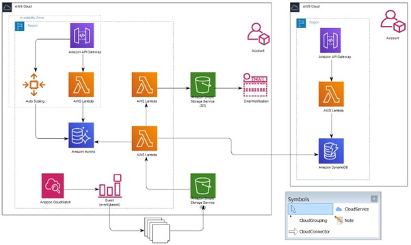
The sample Cloud Architecture Diagram, and the AWS Palettes have been exported into the “initial.qrx” file within the “Models/Cloudservices/AWS/@export” folder of the QW installation (see the AWS categories, and an example of AWS instances in the following chapter).
They must be imported within any repository implementing the “Cloud Services” Meta Model, after having added the “cloudservices” folder and its content into the Models folder of the QLM installation, following the steps listed below:
- Import the initial.qrx
- Close the QLM session
- Open (again) a QLM session
Clicking on the “Technology” button in the bottom left pane of the QLM window, then on the “Show all templates” icon (second icon from left on top of the Repository navigation pane) will provide the user with the list of “CloudServices” templates (“cloudxxx”) as shown in the following picture:
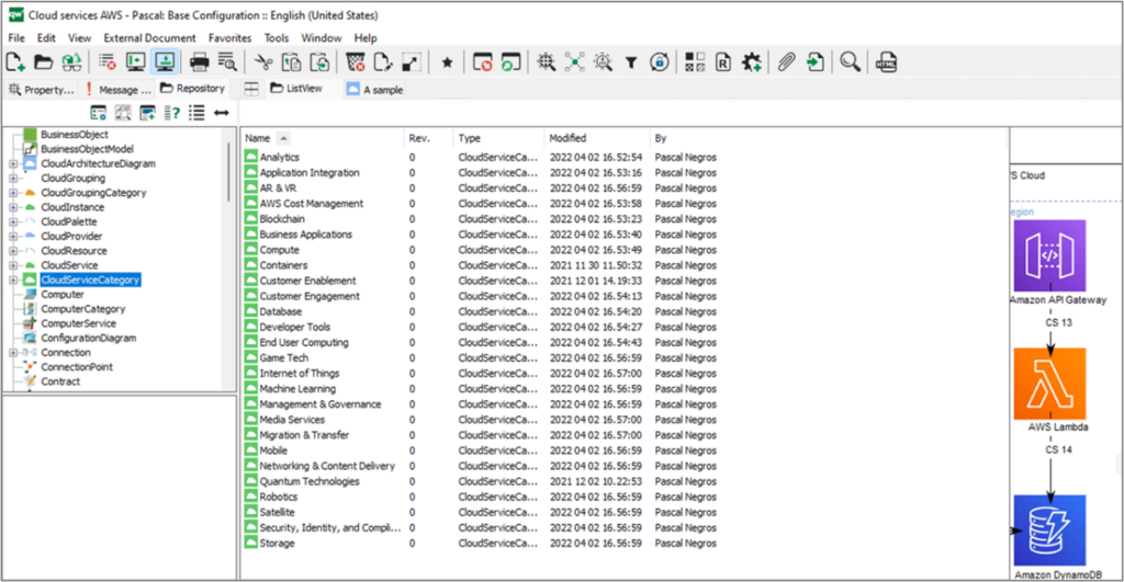
The AWS palette
A ”CloudPalette” diagram editor has been defined to show the AWS cloud services categories and instances used. This diagram editor has no other goal than showing what is used within the AWS palette. It doesn’t contribute to any architecture diagramming or services definition activity.
This diagram editor has been used to validate the “dynamic” appearance of service symbols, based on their category and instance characteristics.
There is a diagram exhibiting the categories, as in the figure below:
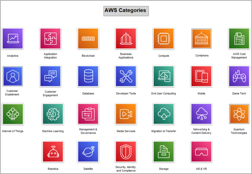
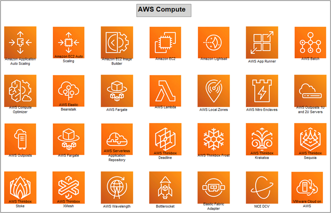
There are as many AWS Instances Palettes as defined to be used. Double clicking on a Category symbol (“CloudServiceCategory”) will show a link to the
corresponding Instances Palette. An example of Instances Palette is given in the figure:
Using the Cloud Services Meta Model
The goal in using this Meta Model, is not only to describe and manage the cloud architecture knowledge, but also to relate the described and modeled cloud services elements to the Enterprise Architecture elements which have been defined, described, modeled prior to define the operational cloud implementation.
The guidance provided below is based on a set of use cases which aim at defining, describing and modeling a “Cloud Architecture Diagram”, and the embedded “Groupings”, Services and Flows, as well as managing the reference relationships to Enterprise Architecture elements.
Defining a “Cloud Architecture Diagram”
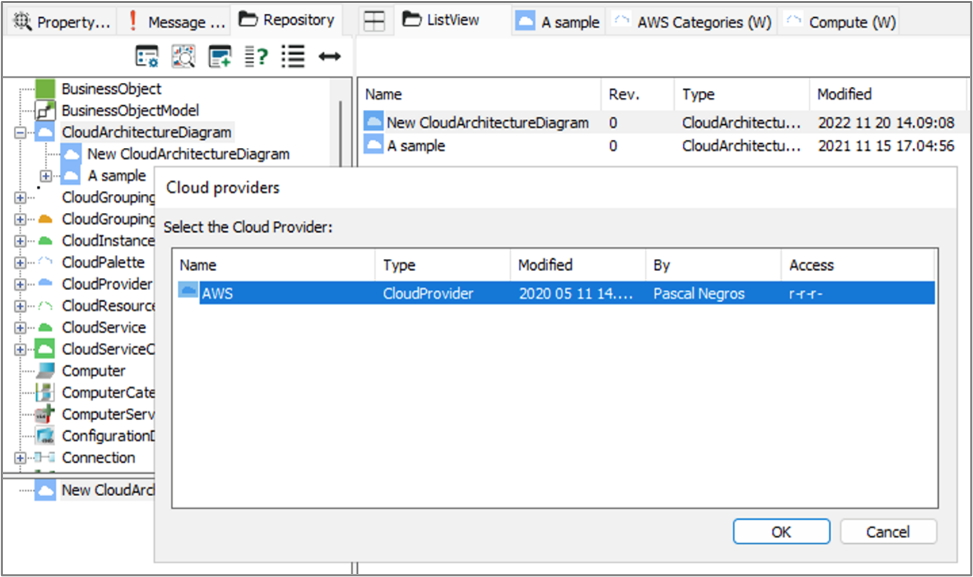
The QLM user creates a new “CloudArchitectureDiagram” the same way as for any other diagram he/she is used with. Then by opening this diagram for the first time, the user is asked to associate it to the Cloud Provider as on the figure below.
The following steps are explained in our Cloud Architecture Diagram.