Firewall

Purpose: The purpose of the Firewall template is to document network zones designated by firewalls.

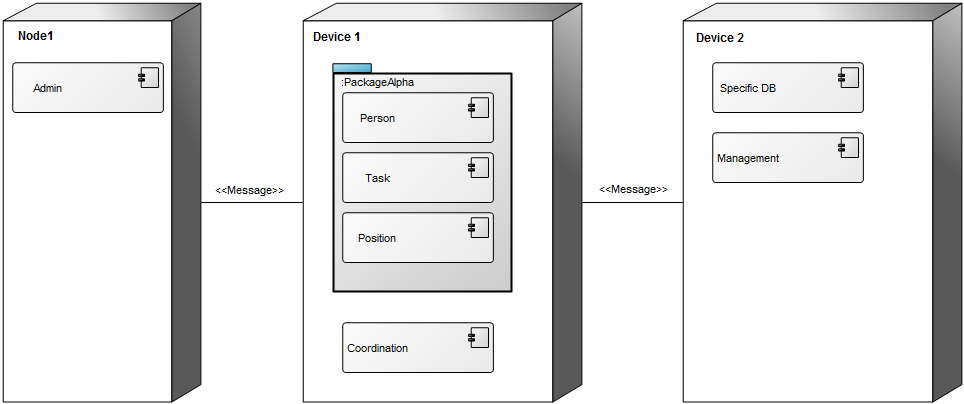
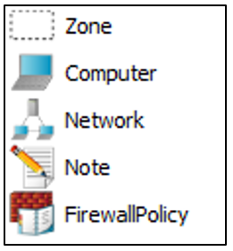
Core concerns: The Firewall template enables you to model Zones, Computers, Networks and Firewall Policies to create a model of a firewall. A firewall is used to control the communication between different networks, typically for security reasons.

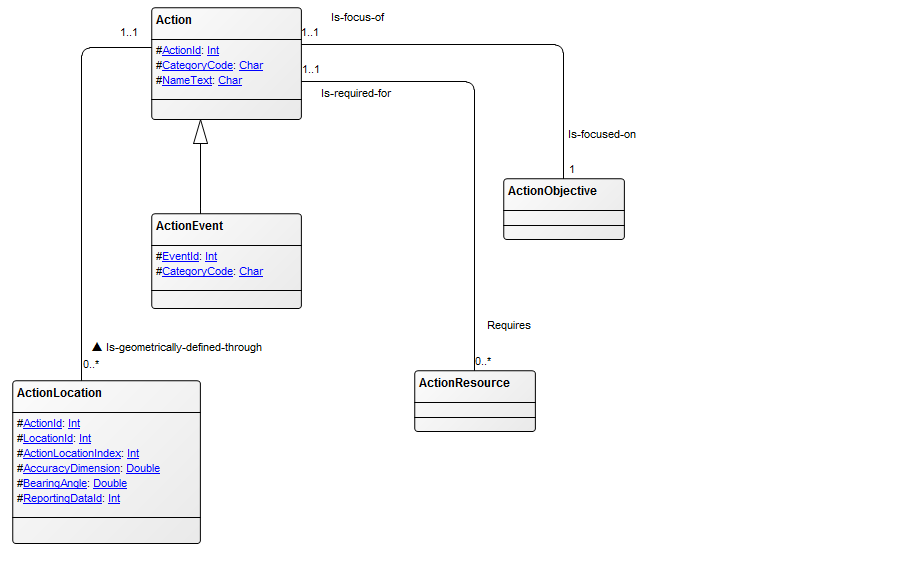
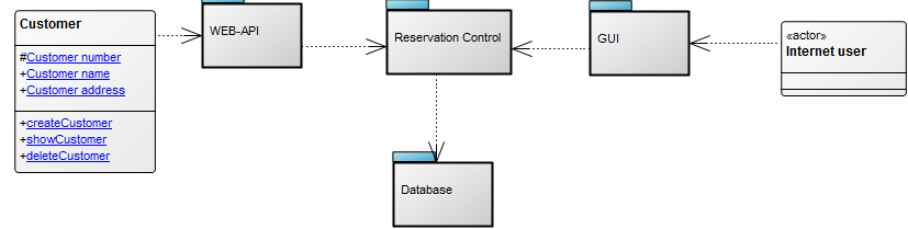
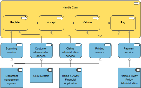
Graphical representation of objects:

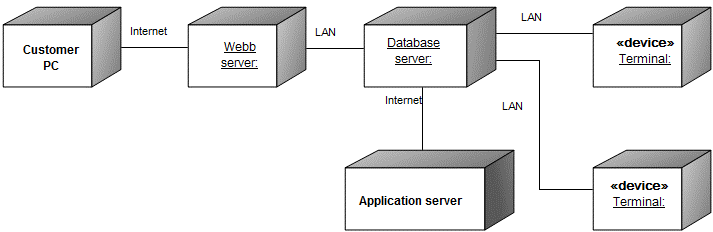
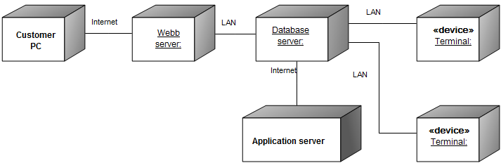
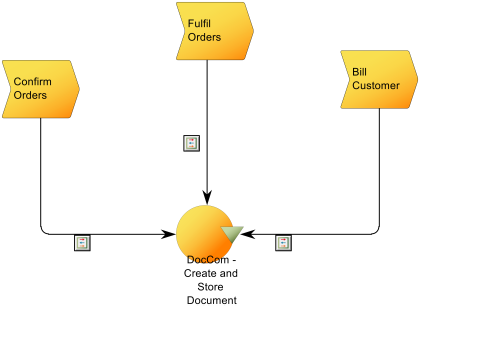
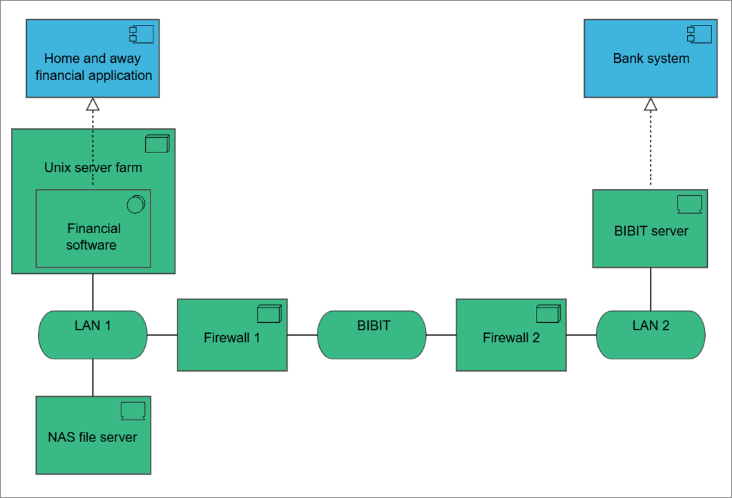
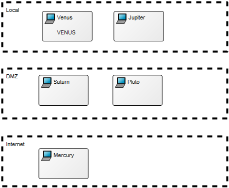
A Firewall diagram will typically show the Zones of the firewall and the communication policies/rules (Firewall Policies) that exist between the zones. Below, you can see an example of a Firewall diagram containing Zones and Servers (represented by the Computer object):

Firewall_1

Relation to other templates: The Firewall template is a technology template and related to the Infrastructure Diagram.

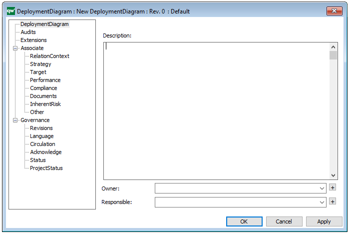
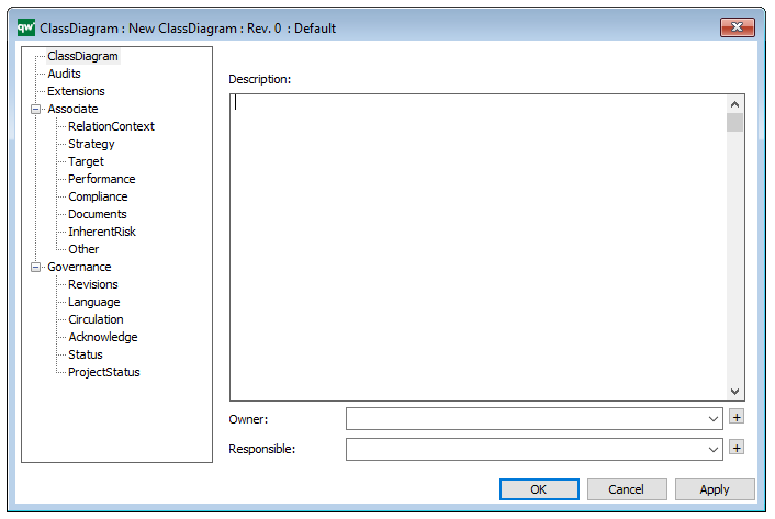
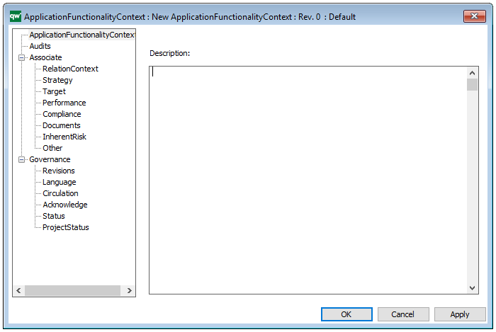
Properties and metadata: The Firewall template ­­­­can for example retain the following information:

  • A description of the diagram
  • Link to Vendor and Hardware
  • Link to servers
  • Contract information
  • Details about resources, costs and benefits
  • Audits (auto generated information regarding its current state and access rights)
  • Associated documents, diagrams and other objects
  • Inherent Risk detailing risk considerations
  • Governance information detailing information about the published diagram and who has been involved in the approval of the diagram


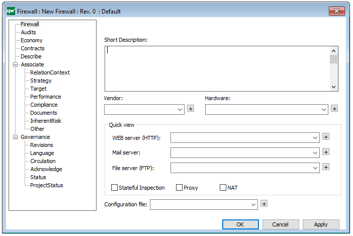
The above picture shows the properties dialogue window for the Firewall template, where you can view and edit the diagram’s properties in QualiWare Lifecycle Manager.

Deployment Diagram

Purpose: The purpose of the Deployment Diagram is to document the configuration of run-time processing nodes and the components they contain.

Core concerns: The Deployment Diagram template is structural UML diagram that enables you to model Packages, Components, Artifacts, Instance Specifications, Properties, Nodes, Devices, Execution Environments, Deployment Specifications, Objects, Classes, Interfaces, and Annotations. They can then be connected through Association, Dependency, Generalization, Deployment or Manifestation.

The Deployment Diagram models how the different hardware component and software components are connected. Below you can see an example of a Deployment Diagram for a booking service:

DeploymentDiagram_1

In the next example, you can see how Packages and Components would be included in a Deployment Diagram:

DeploymentDiagram_2

Relation to other templates: The Deployment Diagram is, as a component model, part of the application domain on the operational level. As such, it offers a complimentary view to those of the Application Architecture Diagram, Class Diagram, Component Diagram, Data Flow Diagram, Data Mapping Diagram, Data Replication Diagram, Sequence Diagram, State Event Diagram, Structure Chart, and Use Case Diagram.

Properties and metadata: The Deployment Diagram can for example retain the following information:

  • A description of the diagram
  • Link to the owner of the diagram
  • Link to the one responsible for the diagram
  • Links to extensions such as Stereotypes and Constraints
  • Audits (auto generated information regarding its current state and access rights)
  • Associated documents, diagrams and other objects
  • Inherent Risk detailing risk considerations
  • Governance information detailing information about the published diagram and who has been involved in the approval of the diagram

The above picture shows the properties dialogue window for the Deployment Diagram where you can view and edit the diagram’s properties in QualiWare Lifecycle Manager.


Class Diagram

Purpose: The primary objective of the Class Diagram template is to visually represent and document the structural components of a system utilizing the Unified Modeling Language (UML). Displayed below is an example of a straightforward Class Diagram:

ClassDiagram_2

Core concerns: The Class Diagram effectively captures the various classes within a system, their attributes, operations, and the relationships between classes and other objects, such as packages. This comprehensive representation enables a clear understanding of the system’s structure, promoting efficient communication among stakeholders and facilitating system design and maintenance.

Example: In the Class Diagram below, the relationships between the classes “Customer” and “Internet User” and the packages “WEB-API”, “Reservation Control”, “GUI” (Graphical User Interface), and “Database” are illustrated. This example highlights the connections among different components and provides a visual overview of how they interact within the system:

ClassDiagram_1

Relation to other templates: The Class Diagram presents a detailed structural view of information. It can for example be a decomposition of an Information System which typically is presented in an Application Architecture Diagram. If a Class Diagram becomes too complex or large, a Package Diagram, where the classes are grouped into Packages, could be modelled instead.

Properties and metadata: The Class Diagram can for example retain the following information:

  • A description of the diagram
  • Link to the owner of the diagram
  • Link to the one responsible for the diagram
  • Audits (auto generated information regarding its current state and access rights)
  • Extensions regarding constraints and tagged values
  • Associated documents, diagrams and other objects
  • Inherent Risk detailing risk considerations
  • Governance information detailing information about the published diagram and who has been involved in the approval of the diagram

In the picture below you can see the Class Diagrams properties dialogue window, where the information can be viewed and edited:


Application Usage Viewpoint : Archimate

Purpose: Designing, deciding

Concerns: Consistency and completeness, reduction of complexity

Scope: Multiple layer/Multiple aspect

The application usage viewpoint describes how applications are used to support one or more business processes, and how they are used by other applications. It can be used in designing an application by identifying the services needed by business processes and other applications, or in designing business processes by describing the services that are available. Furthermore, since it identifies the dependencies of business processes upon applications, it may be useful to operational managers responsible for these processes.

Abstraction Level
Coherence

Layer
Business and application layers

Aspects
Behavior, active structure, passive structure

ApplicationUsageViewpoint_1

Application Functionality Context

Purpose: The purpose of the Application Functionality Context template is to document the in which Activities and/or Business Processes a given Application Functionality is used.

Core concerns: The Application Functionality Context template can be used to create graphical views showing where Application Functionalities are used. The template enables you to model Application Functionalities, Activities and Business Processes. The Business Processes and Activities are connected to Application Functionalities using Functionality Usage.

Below, you can see an example of an Application functionality contest diagram, where the context for the DocCom – Create and Store Document functionality is shown:

The diagram shows which Business Processes use the Application Functionality as well as which Information System delivers it.

Relation to other templates: To map applications hardware, the Application Architecture Diagram or Infrastructure Diagram template should be used. The Application Functionality Context template graphically connects functionalities of Information Systems to the Processes and Activities in which they are used. It offers an additional view to Application Architecture Diagrams, Workflow Diagrams, Business Process Diagrams and Business Process Networks.

Properties and metadata: The Application Functionality Context template ­­­­can for example retain the following information:

  • A description of the diagram
  • Audits (auto generated information regarding its current state and access rights)
  • Associated documents, diagrams and other objects
  • Inherent Risk detailing risk considerations
  • Governance information detailing information about the published diagram and who has been involved in the approval of the diagram

The above picture shows the properties dialogue window for the Application Functionality Context template where you can view and edit the diagram’s properties in QualiWare Lifecycle Manager.

Implement Deployment Viewpoint :ArchiMate

Concerns: Structure of application platforms and how they relate to supporting technology
Purpose: Designing, deciding
Scope: Multiple layer/Multiple aspect

The implementation and deployment viewpoint shows how one or more applications are realized on the infrastructure. This comprises the mapping of applications and components onto artifacts, and the mapping of the information used by these applications and components onto the underlying storage infrastructure.

Technology Viewpoint : Archimate

Concerns: Stability, security, dependencies, costs of the infrastructure
Purpose: Designing
Scope: Single layer/Multiple aspect

The technology viewpoint contains the software and hardware technology elements supporting the Application Layer, such as physical devices, networks, or system software (e.g., operating systems, databases, and middleware).

Technology Usage Viewpoint : Archimate

Concerns: Dependencies, performance, scalability
Purpose: Designing
Scope: Multiple layer/Multiple aspect

The technology usage viewpoint shows how applications are supported by the software and hardware technology: the technology services are delivered by the devices; system software and networks are provided to the applications. This viewpoint plays an important role in the analysis of performance and scalability, since it relates the physical infrastructure to the logical world of applications. It is very useful in determining the performance and quality requirements on the infrastructure based on the demands of the various applications that use it.

Information Structure Viewpoint : Archimate

Concerns: Structure and dependencies of the used data and information, consistency and completeness
Purpose: Designing
Scope: Multiple layer/Single aspect

The information structure viewpoint is comparable to the traditional information models created in the development of almost any information system. It shows the structure of the information used in the enterprise or in a specific business process or application, in terms of data types or (object-oriented) class structures. Furthermore, it may show how the information at the business level is represented at the application level in the form of the data structures used there, and how these are then mapped onto the underlying technology infrastructure; e.g., by means of a database schema.