CPM Diagram

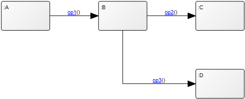
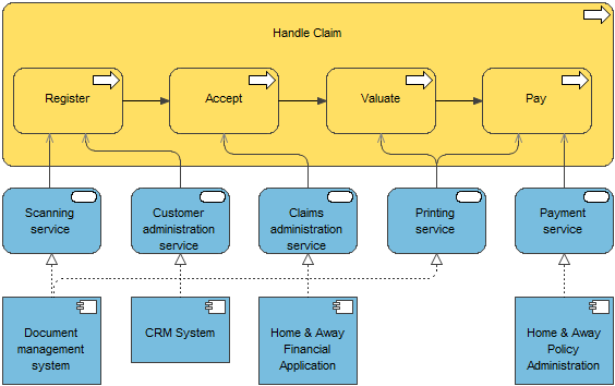
Purpose: The Purpose of the Critical Path Method Diagram (CPM Diagram) is to reveal the critical path through a project, i.e. the list of activities that needs special attention since a delay in these activities will delay the whole project.

Core concerns: The CPM Diagram enables you to model Project Activities and connect them with Activity Paths. The Project Activities are then enriched with information about latest and earliest dates for start and finish as well as information about duration and slack for each Project Activity.

This makes it possible to calculate the probability of finishing the project within the planned timeframe, and to successively improve and detail the plan.

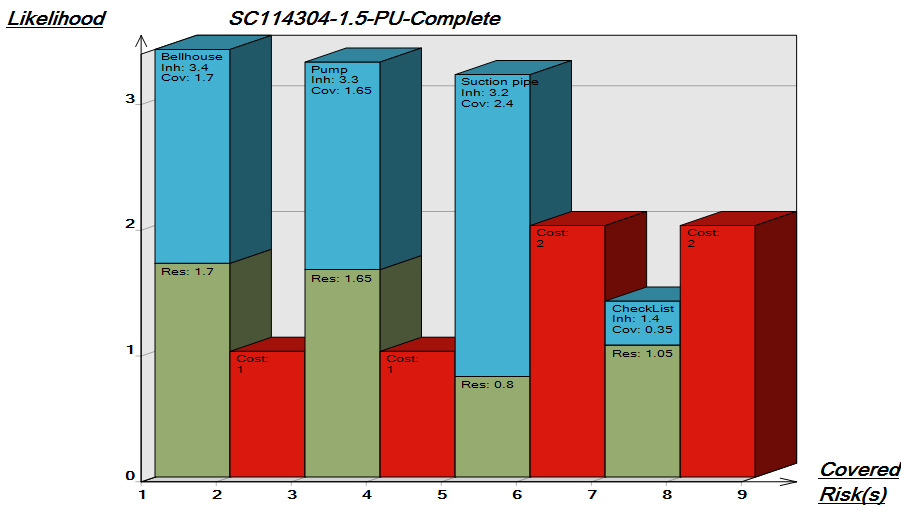
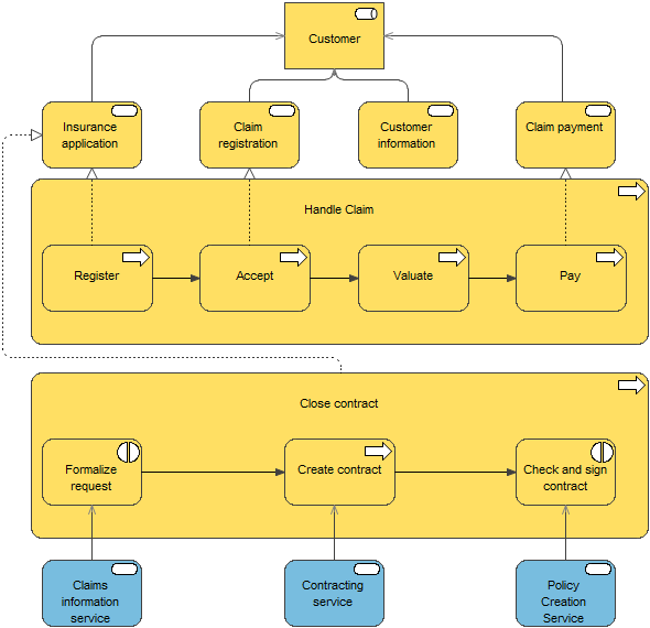
Below, you can see an example of a CPM Diagram about how to develop an organization to support a strategic change. It concerns the incoming and outgoing flow of employees as well as their training across several locations:


CPMDiagram_2

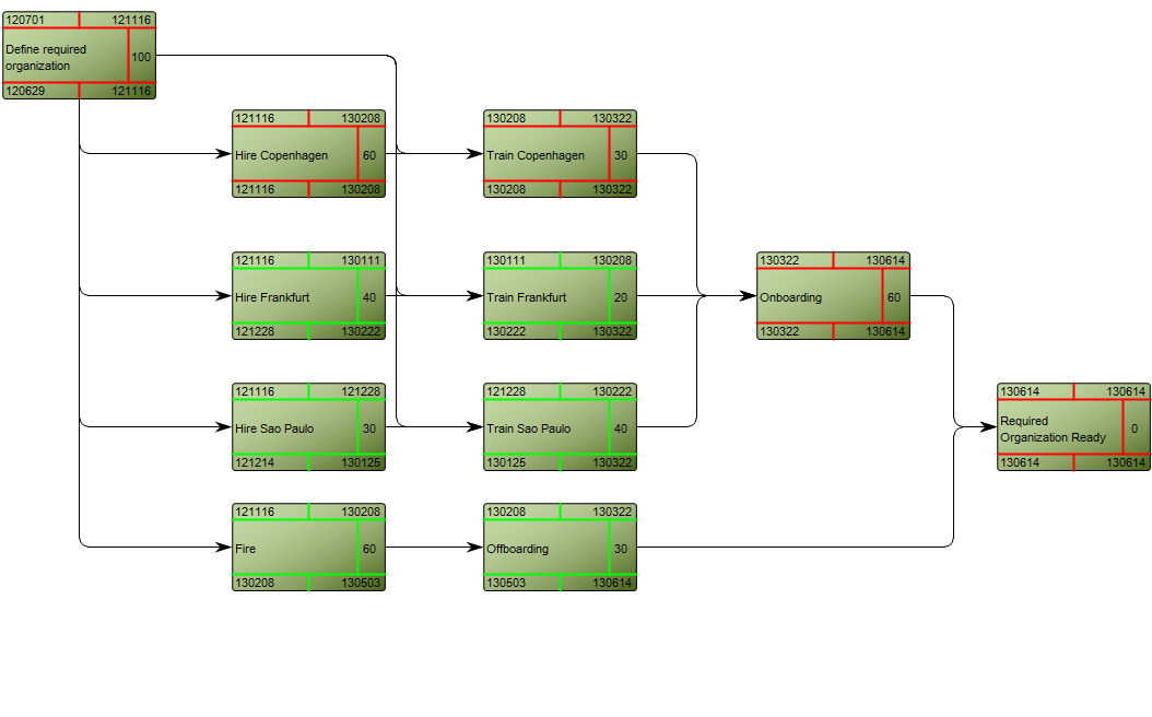
As you can see, the critical path is marked with red.

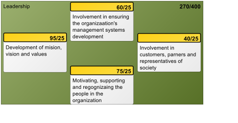
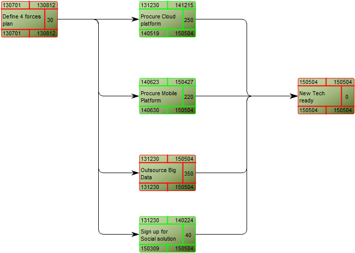
The following example is of a technology roadmap, where the critical path shows the three most critical project activities for on-time completion:

Other functionalities: A Calendar can be linked to the Property Dialog of the diagram showing holidays for the project.

Relation to other templates: The CPM Diagram template should be used after a project has been broken down into Project Activities. As such, it can be a decomposition of a Project Activity from a Business Canvas, Value Proposition, Work Model, Strategy Model or Innovation Canvas.

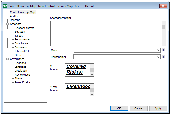
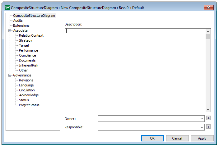
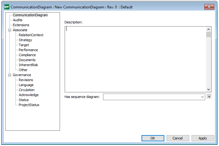
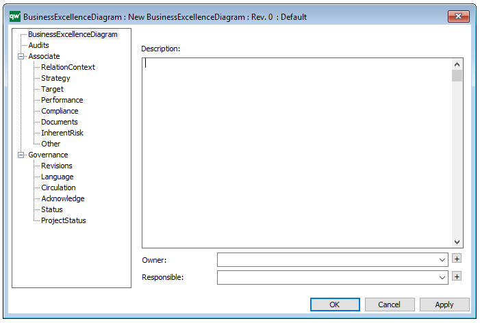
Properties and metadata: The CPM Diagram ­­­­can for example retain the following information:

  • A description of the diagram
  • Link to owner
  • Link to responsible
  • Link to calendar
  • Audits (auto generated information regarding its current state and access rights)
  • Associated documents, diagrams and other objects
  • Inherent Risk detailing risk considerations
  • Governance information detailing information about the published diagram and who has been involved in the approval of the diagram

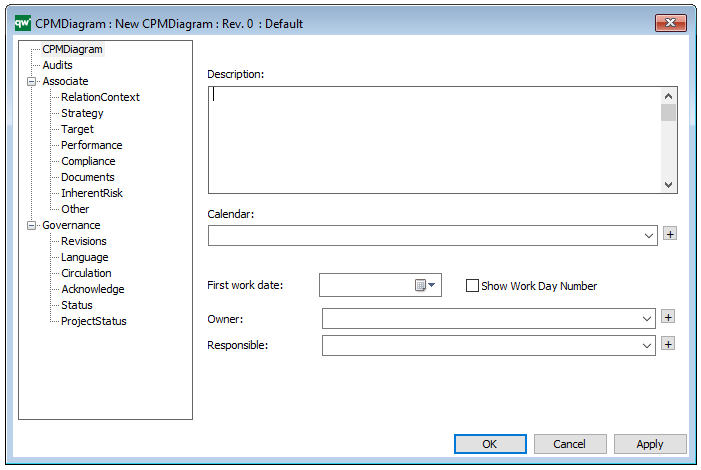
The above picture shows the properties dialogue window for the CPM diagram where you can view and edit the diagram’s properties in QualiWare Lifecycle Manager.

Control Coverage Map

Purpose: The purpose of the Control Coverage Map is to provide an overview of uncovered risks, residual risks and potential cost of the risk occurring.

Core concerns: The Control Coverage Map concerns itself with Financial Risk Management and is created using the Actions tabs in QLM. It can be created based on the information in a Risk Heatmap or by using information from a diagram which contains risks that also have control actions.

Below, you can see an example of a Control Coverage map for four risks related to a Bellhouse, a Pump, a Suction pipe and using Check lists:

ControlCoverageMap

The Blue column represents the likelihood of the risk before the control action, the green column represents the likelihood of the risk after the implementation of a control action. The red columns represent the estimated cost if the risk is realized.

Relation to other templates: The Control Coverage Map presents graphical views of information from other diagrams the same as the Heatmap, Business Charts and the Graphical Matrix. It can be used by any diagram containing Activities with attached risks that have control activities.

Properties and metadata: The Control Coverage Map ­­­­can for example retain the following information:

  • A description
  • Link to the owner
  • Link to the one responsible
  • Graphical specification for the headers of the X-axis and Y-axis
  • Audits (auto generated information regarding its current state and access rights)
  • Associated documents, diagrams and other objects
  • Inherent Risk detailing risk considerations
  • Governance information detailing information about the published diagram and who has been involved in the approval of the Control Coverage Map

The above picture shows the properties dialogue window for the Control Coverage Map template where you can view and edit the template’s properties in QualiWare Lifecycle Manager.

Configuration Diagram

Purpose: The purpose of the Configuration Diagram template is to document a well-defined combination of documents and files to enable an explorer functionality.

Core concerns: The Configuration Diagram template enables you to model Document Categories, External Documents, and Document Revisions (which store references to files containing a revision of an External Document).

The Configuration Diagram should be used to link external documents like CAD-files, word processor documents, spreadsheets etc. including the applications that must be used to view or modify the documents, to the repository.

Other functionalities: Controlling paper documents and their distribution is also possible with this diagram type.

The diagram contains embedded revision control of the external documents. This functionality is based on the following placement of the repository related documents:

Directory structure example:
c:\qwc\
. db\…
. demos\…
. guides\…
. models\…
. Projects\
. . repdb1\…
. . repdb2\…
. . …
. . repdbx\
. . . in\…
. . . out\…
. . . Docs\< here are all related documents placed >

Relation to other templates: The Configuration Diagram can be contained in a Workflow Diagram, be linked as ‘Relevant Documentation’ for a Project Activity and be a decomposition of a Business Scope.

Properties and metadata: The Configuration Diagram template ­­­­can for example retain the following information:

  • A description of the diagram
  • Link to the owner of the diagram
  • Link to the one responsible for the diagram
  • Audits (auto generated information regarding its current state and access rights)
  • Associated documents, diagrams and other objects
  • Inherent Risk detailing risk considerations
  • Governance information detailing information about the published diagram and who has been involved in the approval of the diagram

The above picture shows the properties dialogue window for the Configuration Diagram template where you can view and edit the diagram’s properties in QualiWare Lifecycle Manager.


Composite Structure Diagram

Purpose: The purpose of the Composite Structure Diagram template is to document the internal structure of a class, Class interactions with the environment and behavior of collaborations. The Composite Structure Diagram is part of the UML version 2.5.

Core concerns: The Composite Structure Diagram enables you to model Collaborations, Collaboration Use, Properties, Classes, Interfaces and Ports. These elements can be connected by Connectors, Dependencies, Interface Realizations and Usage.

Below, you can see an example of a Composite Structure Diagram for a car safety inspection:  

The Diagram shows internal structure of the Car-safety inspection class as well as the behavior of collaborations and the different classes’ interactions.

Relation to other templates: The Composite Structure Diagram is part of the UML templates QualiWare supports along with the Activity Diagram, Communication Diagram, Deployment Diagram, Class Diagram, State Diagram, Package Diagram, Component Diagram, Sequence Diagram, Use case diagram and Timing Diagram.

The Composite Structure Diagram can be defined as the components content along with the Component Diagrams, Class Diagrams, Classes, and Interfaces. The Component Object is a representation of a physical part from the system specification.

Properties and metadata: The Composite Structure Diagram ­­­­can for example retain the following information:

  • A description of the diagram
  • Link to the owner of the diagram
  • Link to the one responsible for the diagram
  • Extensions (Stereotypes, constraints and tagged values)
  • Audits (auto generated information regarding its current state and access rights)
  • Associated documents, diagrams and other objects
  • Inherent Risk detailing risk considerations
  • Governance information detailing information about the published diagram and who has been involved in the approval of the diagram

The above picture shows the properties dialogue window for the Composite Structure Diagram where you can view and edit the diagram’s properties in QualiWare Lifecycle Manager.

For more information: about the UML, please visit the Object Management Group’s Website, where you can find the complete specification.

Communication Diagram

Purpose: The purpose of the Communication Diagram template is to document interactions between objects or parts, focusing on sequenced messages.

Core concerns: The Communication Diagram template is a simplified UML 2.0 alternative to the UML Collaboration Diagram. It enables you to model Lifelines and Annotation, which can be connected by messages.

Below you can see a simple example of a Communication Diagram:

CommunicationDiagram_1

Relation to other templates: Usually, Communication Diagrams would be modeled using information from Class Diagram, Sequence Diagram, and Use case diagram. It is related to the other UML interaction diagrams: Sequence Diagram, Interaction overview diagram and Timing Diagram.

While the Communication Diagram show much of the same information a Sequence Diagram does, the Communication Diagram conveys which elements each one interacts with better, while sequence diagrams show the order in which the interactions take place more clearly.

Other UML diagrams that QualiWare support include: Activity Diagram, Communication Diagram, Deployment Diagram, , Composite Structure Diagram, State Diagram, Package Diagram, Component Diagram, Composite structure Diagram, and Object Diagram.

Properties and metadata: The Communication Diagram ­­­­can for example retain the following information:

  • A description of the diagrams
  • Link to related sequence diagram
  • Extensions (Stereotype, Constraints and Tagged values)
  • Audits (auto generated information regarding its current state and access rights)
  • Associated documents, diagrams and other objects
  • Inherent Risk detailing risk considerations
  • Governance information detailing information about the published diagram and who has been involved in the approval of the diagram

The above picture shows the properties dialogue window for the Communication diagram, where you can view and edit the diagram’s properties in QualiWare Lifecycle Manager.

For more information: about the UML, please visit the Object Management Group’s Website, where you can find the complete specification.

Business Process Cooperation Viewpoint : Archimate

Purpose: Designing, deciding

Concerns: Dependencies between business processes, consistency and completeness, responsibilities

Scope: Multiple layer/Multiple aspect

The business process cooperation viewpoint is used to show the relationships of one or more business processes with each other and/or with their environment. It can be used both to create a high-level design of business processes within their context and to provide an operational manager responsible for one or more such processes with insight into their dependencies. Important aspects of business process cooperation are:

  • Causal relationships between the main business processes of the enterprise
  • Mapping of business processes onto business functions
  • Realization of services by business processes
  • Use of shared data

Each of these can be regarded as a “sub-viewpoint” of the business process cooperation viewpoint.

BusinessProcessCoopViewpoint.docx

Business Excellence Diagram

Purpose: The purpose of the Business Excellence Diagram template is to describe a measuring tool based on The European Foundation for Quality Management Excellence Model (EFQM).

Core concerns: The Business Excellence Diagram enables you to model Business Scopes, Criterion and Sub Criterion. These aspects can then be connected by Criterion Influencers.

Below, you can see an example of a Business Excellence Diagram for the Leadership of an organization. The diagram is structured according to the EFQM and shows the overall scores for the leaderships performance:

Other areas covered in the EFQM are Policy & Strategy, People, Partnerships & Resources, Processes, Customer Results, People Results, Society Results and Key Performance Indicators.

Relation to other templates: The Business Excellence Diagram is a strategic template that is complimentary to the Business Capability Model, Stakeholder Model, Business Canvas, and Strategy Model

Properties and metadata: The Business Excellence Diagram ­­­­can for example retain the following information:

  • A description of the diagram
  • Link to the owner of the diagram
  • Link to the one responsible for the diagram
  • Audits (auto generated information regarding its current state and access rights)
  • Associated documents, diagrams and other objects
  • Inherent Risk detailing risk considerations
  • Governance information detailing information about the published diagram and who has been involved in the approval of the diagram

The above picture shows the properties dialogue window for the Business Excellence Diagram template, where you can view and edit the diagram’s properties in QualiWare Lifecycle Manager.

For more information: To learn more about the EFQM, please visit their website, where you can also find an overview of the EFQM Excellence Model.

Browser Diagram

Purpose: The purpose of the Browser Diagram template is to build a structure for reports in QualiWare.

Core concerns: The Browser Diagram template allows you to build a graphical representation of a reports structure, from which it will then generate a code for the system to execute. The symbols available in the Browser Diagram template are: Browser Filter, Browser Action, Browser All and Browser Source. They can be connected by Browser Relation, Browser Back Relations and Browser Graphic Relations.

Several Browser Diagrams are included in the installation of QualiWare. Below, you can see an example of a Browser Diagram for a Business Process Network:

The Following is a Browser Diagram for Audit Planning:

BrowserDiagram_1

Relation to other templates: The Browser Diagram template is used for QualiWare platform customization and is as such related to templates such as the Generic Query, Query Design.

Properties and metadata: The Browser Diagram template ­­­­can for example retain the following information:

  • A description of the diagram
  • Audits (auto generated information regarding its current state and access rights)
  • Associated documents, diagrams and other objects
  • Inherent Risk detailing risk considerations
  • Governance information detailing information about the published diagram and who has been involved in the approval of the diagram

The above picture shows the properties dialogue window for the Browser Diagram template, where you can view and edit the diagram’s properties in QualiWare Lifecycle Manager.


Application Usage Viewpoint : Archimate

Purpose: Designing, deciding

Concerns: Consistency and completeness, reduction of complexity

Scope: Multiple layer/Multiple aspect

The application usage viewpoint describes how applications are used to support one or more business processes, and how they are used by other applications. It can be used in designing an application by identifying the services needed by business processes and other applications, or in designing business processes by describing the services that are available. Furthermore, since it identifies the dependencies of business processes upon applications, it may be useful to operational managers responsible for these processes.

Abstraction Level
Coherence

Layer
Business and application layers

Aspects
Behavior, active structure, passive structure

ApplicationUsageViewpoint_1